MOHPA Radiant Overview
General
� Patches/Curves have been eliminated
� Old MOHAA style terrain has been removed
� Rendering is now optimized by efficient use of selection groups and hiding geometry
� Props Dialog on �P� key
� Radiant Save times are much improved
� Prefabs have been restored
� PSD layers are visibile inside the editor using the Misc->Info Layer option
� Alt-dragging results in SelectCompleteTall
� You can select parts of a terrain using a brush.� Create a brush and then choose Select->Select Terrain Via Brush
� Select all of �x� algorithms are now very fast�
Important Notes
� Your map file is required to have a physical brush placed somewhere in the world space to be ran in-game.�����
� Each Quad of your terrain is limited to 2 additional textures on-top of your base texture
� Take caution when using the undo feature.
Old Files:
terrainName.ter � contains the runtime version of the terrain
terrainName.r32 � A raw full resolution version of the heightfield
terrainName.lvl � the LevelEdit file which contains a native version of the terrain
New Files:
terrainName.ter � contains the runtime version of the terrain
terrainName.raw � A raw full resolution version of the heightfield
terrainName.alpha � A file that contains the texture painting values at the heightfield resolution.
*.stamp - saved heightmap info and the accompanying heightmap mask. These are the saved selections
The new Radiant will export .R32 files for compatibility and world machine
New Worldspawn
Parameters
- Sky � MOHPA no longer uses sky
portal brushes for displaying skies, now they are generated procedurally
using parameters within Radiant.�
This worldspawn parameter specifies which of the textures in the
Game\Main\Textures\Sky folder will be used
- Sky_Altitude
- Sky_Extent
Browsing
New to Radiant is the ability to use and create Browse groups � the purpose of which is to more efficiently organize assets used for the different missions.
After you start Radiant for the first time, you will enter in your Radiant Preferences much as before.� After that, you will see the Project Setting Dialogue.� Here you can now add new browse groups, remove existing ones, or change the directory that the browse group points to.
Once you enter Radiant, there is a new Browse menu command, which you can use to load in groups of assets designed for each mission.

Terrain Creation
and Manipulation
Texturing has also been changed significantly and allows the user much more flexibility and removes many of the rigid constraints involved with applying textures on terrain in the past.
- To create a new piece of terrain, choose File->New Terrain
- To enter terrain editing mode, hit Ctrl+Alt+T, or choose Edit->Terrain Mode from the menu.� This will bring up the terrain editing toolbox, and remaps a few keys to terrain-specific operations.
Heightfield Tab
�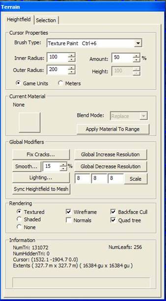
When you are in this mode, your cursor changes to a disk and you can now modify your terrain with a variety of controls.� Here are descriptions for all the Terrain Controls
Cursor Properties
Brush Type � Select different terrain operations to modify the appearance of your terrain with the cursor.
- Vertex Height (CTRL+1)
Use this command to raise or lower your terrain within the cursor in the 3D or 2D windows by clicking the left mouse button.� The amount affects how much the terrain will be altered by your mouse click.� Positive Height values raise the terrain, negative values lower it.� A larger inner radius will apply the
- Bring to Height (CTRL+2)
As you move the red dot representing your cursor across the surface of your terrain, you will see the disk representing the inner and outer radius matches the height of the current section of the terrain.� Clicking the Left Mouse button in this mode will bring the terrain within the cursor disk to the height of the center of the disk.
This operation will set the terrain within the cursor to the value entered in the Height field
This will smooth the terrain within the cursor radius.
- Vertex Noise (CTRL+5)
This will add noise to the terrain within the cursor radius
- Cut Area (CTRL+X)
This will cut the terrain underneath the cursor, leaving the area flat
- Copy Area (CTRL+C)
This will make a copy of the terrain underneath the cursor, leaving the area untouched.
- Paste Area (CTRL+V)
This will place a previously cut or copied section of terrain into the area under the cursor.� How this is applied to the terrain is dependent on the Blend Mode setting.� See the Current Material Section for more details.
- Texture Paint (CTRL+6)
This will paint the material shown in Current Material box to the area within the cursor radius, but only if the Material has been added to that quad.� See the Current Material section for more details.
- Texture Unpaint(CTRL+7)
This will remove the currently selected material from the quad and replace it with the base texture.� In order to repaint the material onto the quad, you need to re-add the texture to the quad by using Shift Right Click.
- Increase Resolution
This will increase the resolution of the quad highlighted in red, forming 4 new, higher resolution quads in the same area as the previous quad.
- Decrease Resolution
This will decrease the resolution of the quad highlighted in red, creating a larger, lower resolution quad from the selected quad and 3 other neighboring quads.
- Sync Heightfield to Mesh
The nature of quadtree terrain is that it is defined by continuous data, or a heightfield, that is capable of storing the terrain information in greater resolution and detail than what is actually displayed in Radiant.� By increasing the resolution on quads, the actual mesh more accurately represents the continuous heightfield data.� However, if you wish to discard the high resolution data for a quad on your terrain, and instead replace it with the lower resolution that is shown in Radiant, you can apply this function.� By doing this, you are, in effect, locking in the lower resolution into your heighfield.���
Inner Radius � all the terrain within the inner radius of the
cursor, represented on-screen as the red disk, will receive the effect of the
terrain operation chosen in the Brush Type box uniformly
Outer Radius � The effect of the terrain operation will drop off proportionally
from full affect at the edge of the red inner radius disk to no affect at the
edge of outer radius disk in blue-green.
Amount � Adjust this to control how quickly the terrain operation
is applied to the existing terrain.� High
values alter terrain quickly, low values change it more subtly.
Height � When adjusting the terrain height, positive values will make the terrain go up, while negative values will make it go down.� Making this value very big (or very negative) will have an effect similar to adjusting the Amount.� For operations that involve sampling the current height of your terrain mesh, this will display the current height sampled by the cursor.
Game Units/Meters � This simply switches the units of the preceding 4 parameters from Radiant units to real-world meters.
Current Material
The Current Material section of the interface is where you pick and choose terrain textures.� It also has additional tools that govern how the textures are applied to the terrain, as well as how cut and copied heightfield selections are reapplied to the terrain when pasted
When you are in Texture Paint or Unpaint modes, you can click the square button to the left to access the Material Palette

Initially you will see just the base material of the terrain, which has been given the name Material 0.� To add new materials to paint on your terrain, click the Add button to create a new material, then choose a Texture in the Material Settings.� Except for the base, Materials can be removed from the palette and your terrain here as well.
Texture � Use this to change the texture used for your material layer.� You can also click the button with the ellipsis (�) to access another folder containing custom terrain textures.� These textures must be in .tga format to be used by Radiant.
Collision - You can also adjust the Collision type of the highlighted material.� This will determine the sounds that the terrain will make when walked upon or shot, as well as determine the type of particles it will spawn when bullets strike it.
Texture Scale � this will adjust the scaling of the material texture across your terrain.
Apply Material to Range � this powerful function will allow you to quickly paint a specific material across your whole terrain based on height.� You input a minimum and maximum height, then specify the amount (which is the opacity of the applied material).� This is a great way to quickly apply muddy riverbed textures on the lower parts of terrain, grass in the middle latitude, and rock or snow on peaks and mountains.� Also, by clicking the Everything button, you can quickly apply a single material to your entire terrain.
Blend Modes
����������� Blend modes modify how cut or copied sections of the terrain are reapplied when they are pasted onto the terrain.
- Additive � this will sum the height values of the selection with the height values of the terrain underneath it.��
- Subtractive � this will paste the inverse of the selection onto the terrain.� So if you had a cut or copied a small bump and placed it on a flat surface, it would created an depression.� Conversely, if you cut or copied a dent, it would create a bump when placed.
- Blend - This will sum the height value of the terrain with the height value of the selection proportional to the value of the Amount field.
- Average � This will average the height value of the terrain with the height value of the selection.�
- Replace � this will completely disregard the current height value of the terrain in favor of the height in the selection
Materials and
Quads
����������� Although the new terrain system is powerful, it does have limitations.� Within a quad, you can only have 3 textures applied at once.� The terrain editor is designed to not allow you to paint in excess of this limit.
First, create a terrain and add several materials to your palette.� Now, select one of your materials other than Material 0.� If you attempt to paint it onto a quad, you�ll see a red texture, meaning that the material is locked out from the quad.� In order to paint the material, you have to enable it for that quad.� This can be done by holding down SHIFT+RIGHT CLICK, which brings up a small list displaying all of the materials in your level palette.� A check mark next to the material means it has been enabled in the current quad.� Place a check mark next to your selected material and start painting.
����������� Note, you can also use this same method to disable materials from a quad.� Keep in mind, however, that the texture data is still there, just not displayed (verify this by disabling a quad�s material then reenabling it).� In order to truly removed texture data from a quad, you�ll need to use Texture Unpaint.
Global Modifiers
Fix Cracks � As the resolutions of individual quads are raised and lowered, discrepancies in the resolutions of adjacent quads cause gaps or cracks to appear.� Hitting this button will automatically modify height values along quad borders to stitch these gaps up.
Smooth � this will soften the differences in terrain by the percentage specified
Lighting � This will allow you to specify how your terrain is lit.� Note that this will also updated the worldspawn entity parameters for your level

- Sun Color � the RGB values representing the color of the global sunlight.� Hit the ellipsis button (�) to bring up a color picker dialogue.
- Ambient Light Color - the RGB values representing the color of the ambient light.� Hit the ellipsis button (�) to bring up a color picker dialogue.
- Sun Rotation � What direction the sunlight is coming from
- Sun Elevation � how high (in degrees) above the horizon the sun is pointing (not where the sunlight is coming from).� A value of 0 means the sunlight is pointing north, which is oriented to the right when you are looking at your terrain from the top view.
- Terrain Shadows � must be enable to apply Gaussian blur to the terrain lightmap (any value more than 0 takes more time to process)
- Explain � brings up a dialogue box explaining all the parameters
- Run � process the lightmap (this may take some time)
- Cancel � close the window.
Sync Heightfield to Mesh � just like the cursor brush type, this will discard the high resolution heightmap data used to define the entire terrain and replace it with data at the resolution actually displayed in the editor.
Global Increase Resolution � Increases the resolution of all quads in the terrain
Global Decrease Resolution � Decreases the resolution of all quads in the terrain
Scale � use this to modify the X, Y, and Z dimensions of your terrain.� Use the conversion chart below to determine your desired terrain dimensions
|
Old Terrain Size |
New Terrain Scale |
Size in Game Units |
Size in Meters |
|
512 |
4 |
8192 |
163 |
|
768 |
6 |
12288 |
246 |
|
1024 |
8 |
16384 |
328 |
|
1536 |
12 |
24576 |
491 |
|
2048 |
16 |
32768 |
655 |
|
4096 |
32 |
65536 |
1311 |
|
8192 |
64 |
131072 |
2621 |
|
16384 |
128 |
262144 |
5243 |
Terrain Rendering
Options
Textured � Shows the terrain with textures
Shaded � Shows the current heightmap data
None � Removes terrain from the view
Wireframe � Shows the wireframe of the terrain
Normals � Shows the perpendicular vectors of each vertex of the terrain
Backface Cull � Toggles whether polys under the terrain are displayed or not
Quad Tree � displays the borders of the terrain quads (useful for enabling and painting materials)
2D Rendering
Options
On the toolbar, there is a new button called Terrain in 2D.� It looks like this.
![]()
Clicking it multiple times will toggle the terrain in the 2D view between None, Wireframe, Textured, Shaded, and Quad Tree.� It can also be accessed via hotkey (CTRL+SHIFT+T)
3D Rendering
Options
You can optimize your 3D Preview window by culling out objects within a certain range.� This is accomplished by clicking on the Cubic Clipping button on the toolbar to activate the Cubic Clipping mode.��
![]()
Now you can adjust the range in which you want objects to be clipped out by using the hotkeys SHIFT + pressing [ to decrease the radius or ] to increase the radius.
MOHRadiant now supports collision previewing, which allows the user to view collision attached to models used in your level.� To enable this option, go to the toolbar and hit the View Collision button.
![]()
Static model collision will appear as green in the 3D
Preview window, and models which have physic attributes attached to them will
have gray collision.
Selection Tab
Tools
����������� The Selection tab of the Terrain Editor allows the user to hide and subsequently show individual polygons of the terrain.
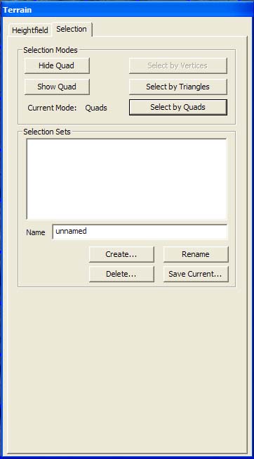
Selection Mode
Functions
At any time when you are editing terrain, you can hold down the SHIFT + Left Mouse Button and drag the mouse over the terrain to select individual polygons.� Individually selected vertices will be highlighted in red.� Polys can either be chosen in Triangle or Quad mode.� It should be noted that a quad in this context differs from our previous definition of a terrain quad, in this instance, it means 2 polygons defined by 4 vertices.��
- Hide Quad � This will hide polygons, creating holes in your terrain.� Only works when polys are selected in Quad Mode.
- Show Quad - This will show previously hidden polygons, which can still be selected with SHIFT+Left Mouse Button.� Only works when hidden polys are selected in Quad Mode.
- Select by Vertices � currently not available
- Select by Triangles � This will select individual polygons and the 3 vertices that define them.� Not currently particularly useful as Hide and Show Quad will not work with polys selected using this method.
- Select by Quads � This selects pairs of polys and the 4 vertices that define them.
Selection Sets
& Stamping
����������� Selection Sets are an alternative to choosing areas of terrain for copying and pasting.� Instead of being defined by the circular cursor, selection sets are determined by selecting individual polygons.�
First, select an area of polys in either the 2D or 3D views using SHIFT + Left Mouse Button.� Then, enter a name in the text field and click Create.� This will create a small piece of terrain, called a stamp, in the maximum rectangular dimensions of the vertices you have selected. �Move the mouse back to your terrain then select the Paste brushtype - you�ll see your terrain cursor along with a red rectangle in the shape of your stamp.� Apply the stamp to the terrain by clicking the left mouse button.
����������� You can create as many stamps as you like as they are persistent and associated with your mapfile, allowing you to create and maintain a palette of terrain shapes for future use.� However, stamps can only be applied additively.
Create � Creates a stamp with the given name.� Can be used to overwrite the contents of the stamp if the name is unchanged
Delete � Remove a stamp from the total group of selection sets
Rename � Rename a stamp
Save Current � Saves your currently selected stamp
����������� Also note that there is a new selection type called Select Terrain Via Brush.� Simply create a brush then right click, and choose Select->Select Terrain Via Brush.� This will select all the vertices underneath the terrain.� This is a great way to select large areas for stamping, but currently it does not allow the terrain to be hidden in this fashion
Undoing Terrain
Operations (CTRL+SHIFT+Z)
Any terrain alteration can be undone by selecting Edit->Undo Terrain Operation or pressing CTRL+SHIFT+Z.
Other Shortcuts
The following keys can be reassigned by overriding them in radiant.ini
(you can also find these commands listed in the Help->Commands list).
���������������
|
FUNCTION |
SHORTCUT |
|
TerrainSelectHeightCursor |
Control + 1 |
|
TerrainSelectBringToHeightCursor
����������� |
Control + 2 |
|
TerrainSelectSetToHeightCursor ��������������� |
Control + 3 |
|
TerrainSelectSmoothCursor ����������������������� |
Control + 4 |
|
TerrainSelectNoiseCursor �������������������������� |
Control + 5 |
|
TerrainSelectPaintCursor� �������������������������� � |
Control + 6 |
|
TerrainSelectUnpainCursor � |
Control + 7 |
|
TerrainSelectIncResCursor ������������ � |
Control + 8 |
|
TerrainSelectDecResCursor ���������������������� � |
Control + 9 |
|
TerrainSelectCutCursor��� ��������������������������� � |
Control + X |
|
TerrainSelectCopyCursor�� ������������� � |
Control + C |
|
TerrainSelectPasteCursor� �������������������������� � |
Control + V |
|
|
|
|
TerrainActivateCurrentCursor
(this is the same as clicking once, especially handy for the copy/paste
cursors) |
Enter |
|
|
|
|
TerrainIncInnerRadius �������������������������������� � |
Shift + ] |
|
TerrainDecInnerRadius ������������������������������ � |
Shift + [ |
|
TerrainIncOuterRadius ������������������������������� � |
] |
|
TerrainDecOuterRadius ����������������������������� � |
[ |
|
|
|
|
TerrainIncAmount ��������������������������� � |
' |
|
TerrainDecAmount �������������������������� � |
; |
|
|
|
|
TerrainIncHeight ����������������������������������������� � |
. |
|
TerrainDecHeight ���������������������������� � |
, |
|
TerrainNegateHeight ���������������������������������� � |
/ |
|
|
|
|
TerrainHideQuad� ���������������������������� � |
H |
|
TerrainShowQuad����� ���������������������� � |
Shift + H |
|
|
|
|
TerrainSelectTriangles �������������������������������� � |
2 |
|
TerrainSelectQuads�������������������������� |
3 |
|
|
|
|
Apply current cursor |
Left mouse button |
|
Paint-Select triangles/quads |
Shift+Left mouse button |
Selecting Objects
����������� By holding down ALT + Left Mouse Button and dragging the mouse, you can now box select brushes, entities, and objects in the 2D view.� This replaces the slightly more inconvenient means of selecting multiple entities in older versions of Radiant, which required you to create a brush as your bounding box, then choose a Selection function like Select Complete Tall, etc..� Although this new selection tool functions just like Select Complete Tool, users can still use brushes and the old selection commands if they desire.
Working With
Objects
Eventually your level will be filled many-many models, and depending on how you placed those models, it can be hard to navigate and select certain models.� To help you manage your models, it is advised you make use of the (H) Hide and (SHIFT+H) Unhide feature, which will allow you to select an object and hide it from view until you need it again.� Additionally, you can use the (J) hotkey to remove the bounding box for each object in your level, which can greatly improve your visibility if you have a lot of models selected.
Regions
Regions are an important tool to learn and use early on.
Whether you isolate off a single object, or half a map, you�ll wonder how you
ever got along without this tool in other editing programs. The selections on
the Region Menu allow the user to isolate, and work on, a subset of the map.
There are innumerable benefits to working in a �regioned� area of the map.� It allows you to work with a few map
components at a time, without the distraction of the rest of the map pieces.
There are several ways
to select a region, by a group selection, by XY map window dimensions (or the
corresponding view in YZ and XZ), or by a few selected map components.
Off
This
returns you back to the full map.
Set XY
Any map components that are inside, or that are touched by the bounds of the XY
Map window are converted into a region. The size or shape of the window does
not matter. This is an excellent way to select are larger subset of your map,
such as a complex room or group of rooms. Any objects selected before regioning
the map remain selected.
Set Tall Brush |
This functions in a similar manner to the group selection command, Select
Partial Tall. Any map components contained within the XY bounds, or touching
the XY bounds of the brush will be regioned off. The selecting brush itself is
discarded.
Set Brush
This functions in a similar manner to the group selection command, Select
Touching. Any map components contained within the XYZ bounds of the brush, or
touching the XYZ bounds of the brush will be regioned off. The selecting brush
itself is discarded.
Set Selected Brushes
If you need to work with just a few objects, this is the option to choose. Select
the objects to be worked upon then select this option. Only those objects are
moved to the region. The selected objects are unselected when the region is
created.
Selection Groups
Selection groups are now �Photoshop� style.� To bring them up, select the �G� key
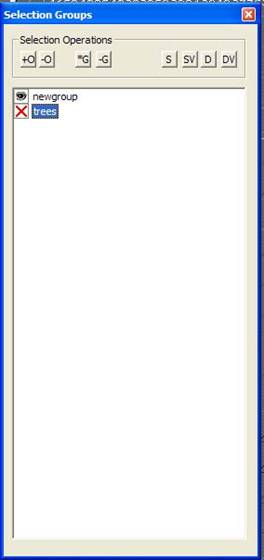
This allows users to more effectively organize groups of objects and entities
*G � Create Group - Allows to create a group and give it a name.� Note that this will not automatically create a group from selected entities, you must add them manually to the group.
-G � Delete Group - Deletes the Highlighted Group
+O � Add Object to Group � Adds a selected object to the highlighted group
-O � Remove Object from Group � Removes selected objects from the highlighted group.� If the objects are a member of more than one group, they will only be removed from the first one in the list.
S � Select
Objects in a Highlighted Group
SV � Select All
Objects in All Groups
D � Deselect
Objects in a Highlighted Group
D � Deselect All Objects in All Groups
The eye icon next to each group name can be clicked to toggle whether or not that group is visible.� Click twice on the text of the groupname you can rename it (if you double click too quickly it won�t do it, click once per second)
New Selection Menu
Functions
Parent
Unparent
Lock � This will prevent a selected entity from being moved.� Other parameters of the entity can be edited in the entity window.
Unlock � This will allow a locked entity to be moved again
Randomize Entities � This new function is very useful for making vegetation look random and non-uniform.
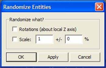
- Rotations � check this box to
randomly apply a rotation to your selected entities (this is 1-dimensional
about the z axis)
- Scale � when checked, you can
enter in a scale value and then a percent variance
Terrain Hug All Entities � All Entities can now be specified to hug the terrain.� This can be extremely useful and time saving for placement of vegetation
Toggle Terrain Hug on
Entity � Turn terrain hugging on or off on specific entities
Toggle Terrain Align
on Entity � Entities can also align themselves with the normals of a
terrain poly.� Use this if you want
vegetation or other assets to grow out of the terrain, not necessarily up or
down.
Named Group Operations � This is similar to the functions provided in the Selection Group Browser.� They include:
- Select Named Group � Brings up a dialogue to choose one of the named groups in the level
- Add Current Selection to Named Group � Brings up a dialogue to select which of your groups you want to add the selected objects to when you click OK.� You can also click Add/Create to create a new group and add your selected object to it.
- Remove Current Selection from Named Group -
- Create Named Group � This will allow you to create a new selection group
- Delete Named Group � This will allow you to choose a selection group and delete it.
- Show/Delete Empty Groups � This will show all empty groups and
Scatter Tool
����������� The Scatter Tool is another new feature of Radiant that allows designers to use a Photoshop file (.PSD) to literally paint layers of vegetation onto the terrain.� The alpha channels of the layers in Photoshop determines how dense the vegetation is.� Different rules can also be applied to the layers to define how the layers are applied relative to one another.� For example, the grass layer can be adjusted so that it only paints grass objects close to objects in the tree layer, and so forth.� Using this tool can be a very useful way of applying vegetation over a large area quickly.
Creating the Density Map File
First you need to generate a snapshot of the map that need to be scattered.
In Radiant, with map open, select menu �file->Reference Snapshot�. This will generate a snapshot of the top view of the map and ask for saving to a �.tga� file. Make sure the terrain texture is enabled by clicking the �Ter in 2d� button on the toolbar.
Then you open the snapshot file with Photoshop. For each group of models, you create a layer, give it a proper name like �trees�, �rocks� etc. Then you paint in that layer. The image in that layer will later be used as the density map by the scatter. The actual color doesn�t matter, the scatter tool only care about the alpha channel. The area with less transparency will result denser objects in the map. You may use some filters to generate a smooth gradient from different alpha areas. After painting the dense image to all the layers, save the file as a �.psd� file.
Configure Scatter
Go back to Radiant. Select the menu �Scatter->Configure Scatter�. This will bring a dialog like this

The rules file and the density map file controls how the scatter tool put the models in the map. Set the �rules file� field with whatever rule file (�.rul�) you need.� If you do not have a rules file for this map, then entering the name of a file which does not exist will force scatter to create a new �empty� rules file.
Set the �Density map file� field with the psd file you created in last section. Fill in proper values to other fields:
Editing Rules
If you have loaded in a new rule, or you want to do some changes to the rule, click the �Edit rules� button. It will bring in this dialog box.

One rule file contains multiple rules with different name. Use the pull down menu to choose which rule you want to edit, or create new rules, or delete the current rule.
Basic Scatter
Properties
- Layer name: Is the layer you put in the density map with Photoshop.� When a rule is executed, it uses this exact name to look up the correct layer in Photoshop.� The layer name is case sensitive, so the layer name here MUST exactly match the layer name in Photoshop.
- Model/Class: Is the model you want to scatter. This can be either �.gr2� or �.hag� file.� Use the filespec drop down menu in the file open dialog to select either .gr2 or .hag. You can also put the class name here. For example, put �info_pathnode� without quotes will make the scatter tool scattering pathnodes.�
- Distribution: There are three options: none, square, and hexagon. If set this to square or hexagon, the objects will distribute regularly in square shape or hexagon shape. The distance between adjacent objects will be �Exclusion min� value (see below). This option was designed for scattering path nodes, but can be used for other model/class as well.� �None� works best for distributing vegetation.
- Exclusion Distance: This controls the valid distance between instances of a scattered model in the map. For example, with the min set to 1, max set to 2, each model will be at least 1 units away from any other models and be within 2 unites to at least one model.
- Scale:� This will allow the user to specify a range of scaling values to apply to scattered entities in the rule.� Distributed scale differs from random scale in that it is based on a Gaussian function.� If it is used, there will be more entities with a scale closer to the middle of the range than entities with a scale close to the minimum and maximum values of the range.� With Random Scale, the possibilities of getting entities with scale values close to the minimum, middle, and maximum is about the same.
Running Scatter Tool
After you configure the scatter tool, you can run the scatter tool by selecting menu �Scatter->Run Scatter Tool�. This will actually generate the models based on the rules. Or you can select menu �Scatter->Run Scatter Tool (Selected rules)� to select one or more rule from the rule list. Depending on the set up, the running will take several seconds to a minute.
Other Scatter Options
Elevation: These values control the distribution of the models regarding to the elevation of the terrain. Consider the �inner value� and �outer value� as the inner and outer radius of a donut shape. Roughly, all the models will be placed where elevation is between �outer min� and �outer max�. See the drawing:
 �
�
In the area with elevation between inner min and inner max, the models distribute with full density; in the area with elevation between outer min and inner min or between inner max and outer max, the models distribute with density various from 0 to full density.
- Gradient: Similar to the elevation but the values apply�� to the gradient of the terrain.�� These values are measured in degrees.
- Debug color:� This is used for debugging purposes, and its use is not required.
- Start seed: If you are not satisfied with the result of previous running of scatter tool, change this number to any other integer numbers. The scatter tool will then generate the models with another set of random numbers.
- Density Scale:� The density scale setting is a mechanism for manually scaling the density of scattered objects, without having to modify the density map.
- Align object with surface gradient: Not implemented yet.�
- Light weight entity: Not implemented yet.
- Ignore Preexisting objects: If set, scatter tool will ignore the committed objects when scattering new objects. Be sure to alternate the random seeds if you set this option otherwise two groups of the scattered objects will overlap completely.
- Scatter units per game unit:� Scatter always deals with measurements in meters (except for gradients, which are measured in degrees).� This field is a scale value for manually converting map measurement units into meters.
- Vertical Scale:� The vertical scale field is a method for manually converting the values held in the .R32 heightmap file (created from the terrain editor) to meters.� (Note: when running a set of scatter rules, the debug output window will display the min and max values found in the .R32 when it gets loaded.� This can be used to help you calculate the correct setting for this value.� It defaults to 1000, but this may not be correct for the map that you are generating.� If you have any doubts, then contact the artist/designer who generated the terrain, and find out what the min and max heights for the terrain were designed to be)
Using Sub Rules
����������� Sub rules are a way of scattering entities in relation to other scattered entities.� This is useful, for example, when you want to put some small bushes around a tree, or whenever you want to mask the seam where a rock meets the terrain with low tufts of grass.� In order to set it up, you need to first create your parent rule, then the sub rule.� Both rules will reference the same layer in your .PSD file.
To set up the sub rule, select the rule of the parent objects, then click Add under the Sub Rule header to choose which of the rules you�ve created will be your subrule.� The distance parameters under the Subrule header of your parent rule will determine the minimum and maximum distances that the children will be from the parent, not from other children (that value can be determined in the Exclusion Distance parameter of the subrule).
The total sub-model count will be with in the �min object count� and �max object count�.� A random number between these values is chosen to be the maximum number of children that will be scattered around a given� parent.� Note, however, that the min/max object count is not a guarantee.� The program may not be able to place the specified number of objects because of other considerations (gradients, heights, other objects in the way, etc)
Grouping Options
Scattered objects are designed to be easily grouped into Selection Sets.
Other commands in Scatter menu
- Commit selected entities: Commit the entities so they won�t be removed later by scatter tool. The scatter tool removes all the uncommitted entities before it generate new set of entities.
- Uncommit selected entities
- Select all the scattered entities: Select all the entities generated by the scatter tool
- Select only committed entities
- Select only uncommitted entities
Info Layers
Overview
����������� �Terrain
Information Layers� are tools used by designers and artists to allow them to
define a terrain�s regional responses and behaviors based on a 2D bitmap
created in Adobe Photoshop, much like the Scatter tool layers.� They are designed as a �short cut� or �speed
optimization� around otherwise expensive game-side computations and also create
a nice interface to allow visualization of localized environmental effects.
Artists and designers literally �paint� areas of response on separate Photoshop
layers and through appropriate naming of these layers, define how that layer
will affect the in-game environment.�
Radiant also has a feature whereby the artist or designer can
graphically preview these layers (a �PSD� file can be imported) in Radiant�s
�XY Map� (The top-down view).� Radiant
also has the ability to convert a Photoshop �PSD� file into the
�
Supported Layers
�auto_farplane�
����������� This layer controls the distance of the far plane used for visibility culling of geometry in the game. It updates the far plane distance linearly and smoothly in a range defined by the key/value pairs of �auto_farplane_near� and �auto_farplane_far�. The information of the layer data is defined in the range from 0.0 to 1.0. A value of 0.0 is the �All-clear� (no opacity) attribute of a PSD layer pixel. A value from the layer near 0.0 will cause the in-game far plane to approach the value of the �auto_farplane_near� setting. Similarly, a value of 1.0 is the �full bright� (full opacity) attribute of a PSD layer pixel.� Layer values close to 1.0 will cause the in-game far plane distance to approach the value of the �auto_farplane_far� setting.� All values from this layer will apply a far plane distance within the range of these two values.
�obfuscation�
����������� The values in the obfuscation layer serve to attenuate or �dumb down� an AI character�s ability to detect other AI characters and the player. The values in the obfuscation layer range from 0.0 (No obfuscation�clear L.O.S.) to 1.0 (Complete concealment�minimal chance of detection). Calculations to determine �effective detectability� of an obfuscated character also consider the distance between the 2 characters.� Characters farther away have a higher bias of obfuscation whereas closer characters gain less benefit from the values in the obfuscation layer.
�particle_filter�
����������� The particle filter layer allows the artist to control the types of particles that will be produced in different regions of the map. In the �TIK� file for a particle effect, the following directive is issued:
����� originemitter a_particle_effect
����� (
����������� particle_filter
128
����������� �
����� )
����������� This means that when the player character traverses over any section of the particle-filter layer and the value at that location is �128� (NOTE: This layer should be monochromatic), then the particle effect �a_particle_effect�, will begin emitting. When the player character leaves this region, the effect will cease. Using different values for the TIK �particle_filter� directive, a set of up to 256 different effects can be varied throughout a landscape.
Radiant �Terrain Info
Layer� Dialog Options
����������� The �Terrain Info Layer� dialog can be invoked from the main menu by selecting �Misc->Info Layer�. The options on this dialog are:
- Load - This allows the artist or designer to load any PSD file for
viewing and exporting.� The filename
of the PSD file is not important as the TIL Exporter will use the map name
with the �TIL� extension when it creates the resultant output file.
- �Refresh�- This option allows the
designer or artist to quickly reload the current PSD file.� It allows them to bypass the �Open File�
dialog altogether.
- �View� - Selecting this option will
produce a dropdown box containing the names of ALL the layers contained in
the PSD file (Not just TIL layers).�
Selecting any of them will cause that layer to visually overlay in the
�XY Map� top-down map.� Select the
�none� entry to suppress this overlay display.
- �Export� - This option creates the
output TIL file in the same directory as the BSP file. The resultant file
will be of the same filename as the BSP file save for the BSP extension
(It will have a �.TIL� extension).�
This step is required if any changes to the PSD layer are to be
propagated to the game. Note: Only layers with the �TIL_� prefix and a
valid layer name will be exported. The valid layer names to date are �auto_farplane�,
�obfuscation�, �particle_filter�, and �contact_sounds�.
- �Clear� - This option completely
disassociates (unloads from memory) the current PSD file being used.�� If the �View� option was used
previously and is still active, the �XY Map� overlay will disappear as
well.
- �Done� - This option hides the
�Terrain Info Layer� dialog.� It can
be invoked again from the main menu by selecting �Misc->Info Layer�.
Operation Checklist
1) In Radiant, load a map for editing.� In this example, �foo.map�
2) Choose the settings for the �XY Map� that will make it easiest to visualize the terrain from a top-down view (�Grid off�, �TERin2D��etc).
3) From the �file� menu in Radiant, use the �Reference Snapshot� option. You will be prompted to save a TGA file containing an accurate full-map top-down image of your level.
4) Save this TGA image in your �map_source� folder and append the word �ref� to the filename (For clarity).� In this example, save it to �foo_ref.tga�.
5) Open up Photoshop and load this TGA file as your �background� layer
OR
6) Open the PSD file associated with your level (It is OK if it has �scatter� layers in it, these are ignored by the TIL exporter.
7) Create a new layer called �TIL_auto_farplane�.� The �TIL_� prefix is how the TIL exporter recognizes valid layers.
8) Paint an image on this layer (Do not �flatten� the image.� Keep the layers insulated from each other). Save the PSD file.
9) In Radiant, find the �worldspawn� entity and set the key/value pairs for �auto_farplane_near� and �auto_farplane_far� (optional�the defaults are 1000 near and 10000 far).
10) In Radiant on the main menu, select �Misc->Info Layers� and a dialog box will appear.
11) Select the �Load� option and open the PSD file you have just edited.
12) Optionally, you can select the �View� option and a dropdown box will appear. Select the layer you wish to view (�TIL_auto_farplane� is this example.).� You will an overlay of that layer on the �XY Map� top-down window. Select �View->none� to clear it again.
13) Press the �Export� button.
14)
Run
Final Notes:
1) The only PSD layers the TIL exporter will recognize are those with the prefix �TIL_� and with a valid layer name.� At the time of this writing, the valid layer names are �auto_farplane�, �obfuscation�, �particle_filter�, and �contact_sounds�.
2) TIL files have can have a substantial memory footprint. This will be addressed as a memory optimization in the TIL exporter/reader.
3) All �scatter� information and TIL information can coexist safely in the PSD file. This method should be employed so as to reduce the number of source assets associated with any given level.