Technical support:
Maciej Jamrozik, Kacper Michalski, Grzegorz wistowski
Content-related support and correction:
Kacper Michalski, Wojciech Pszczólkowski, Jakub Klarowicz
Documents written by Marek Pszczólkowski were used in some sections
Translation:
Tomasz Gajer
All program names are the trademarks and are properties of their respective owners and
in this document are used for the information purpose.
Copying the document or its part without the author permission is prohibited. All rights
reserved.
Chapter 1 Introduction 1.1 Requirements
To create anything in the ChromEd editor you need to prepare several additional
programs. You will need a graphics processing program e.g. Adobe Photoshop, Point Shop Pro, Corel Photopaint or freeware GIMP. You will also need Corel Bryce. Personally, during the work I used Adobe Photoshop 7 and this program will be my main tool in this document.
In graphics processing program you will create height maps (more information in
chapter about terrain creation in section about the height map) and also make different kind of map adjustments, convert into another graphics formats etc.
In Corel Bryce you will create the color map (more information in chapter about
terrain creation in section about the color map). However, to create more realistic color maps you will use advanced functions of Photoshop.
Of course, apart from all the programs mentioned above you will need the ChromEd
editor and original version of Chrome game. Additionally, you will need some spare time (well, maybe more then `some') and be very patient.
Finally, I just say that even if you hadn't had any experience with programs like
Photoshop or Bryce you don't have to worry! When I started my experience with the ChromEd editor I had never used Photoshop before, not to mention Bryce! I assure you that despite of all that you may create very realistic and playable maps. Some initiative, a good idea and the willingness to realize it is just enough. The only limitation is your imagination! It is advised to use a three button mouse with a roll. Such mouse will really make the work much easier!
In the next chapters I will describe the rules of map creating for the Chrome game,
starting with description of the ChromEd editor itself, through creating the height maps etc. in graphics processing programs, creating of the map logics and to the very advanced operations like Chrome Engine movies creation for your maps or AI activity (in particular it concerns singleplayer maps).
During writing of this document I tried to write it in simple, understandable language
and to keep in the same tone. In my opinion, I achieved it but the final evaluation is yours. I just hope that thanks to this document you will create sensational maps for Chrome game. Moreover, you can always load into the ChromEd editor the maps that were provided with the ChromEd editor and the Chrome game, singleplayer maps and multiplayer as well. This way you can `peep' what and how the professionals did it.
1.2 Chrome game and ChromEd editor
Before you start your work I'd suggest taking a closer look at the content of the
Chrome game directory. Knowing the files location will make the work easier in the future. This is the directory tree of the Chrome game with a short description: \Data\ - in this directory there are all the elements necessary for the game to work (3D
objects, textures, materials etc., and all the single and multiplayer maps), here is the more detailed description of each directory:
\Data\Animations\ - subdirectory with characters animations,
2 \Data\Brushes\ - subdirectory with the brushes used by the Terrain plug-in (plug-ins are be
described in the further part of the document),
\Data\Films\ - subdirectory with all the Chrome Engine movies that are displayed during the game, \Data\HUD\ - subdirectory with all the bitmaps and scripts applying the game's HUD (radar
displayed on the screen, ammo quantity, health level etc.),
\Data\HUDNet\ - subdirectory with the scripts applying multiplayer game's HUD, \Data\Interface\ - subdirectory containing all `helpers' auxiliary objects used only by the
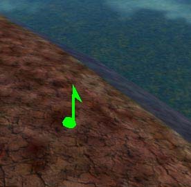
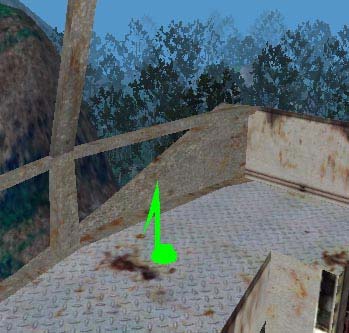
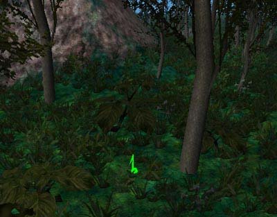
ChromEd editor (not seen during the game itself), symbolizing various kind events e.g. camera (it will help during the movie creation), note (it will help while adding sounds), flag (it will help during setting the checkpoints for AI), bulb (representing light source) etc.
\Data\Levels\ - subdirectory with all singleplayer maps, each map is contained in separate
subdirectory, if you create a singleplayer map you will have to put it in this very subdirectory,
\Data\LevelsNet\ - subdirectory with all multiplayer maps, each map is contained in separate
subdirectory, if you create a multiplayer map you will have to put it in this very subdirectory,
\Data\Materials\ - subdirectory with the materials (special textures) e.g. trees, grass, water,
etc., you will use materials very often to create e.g. water on your map,
\Data\Menu\ - subdirectory with the files that describe the Chrome game menus, \Data\Meshesh\ - subdirectory with meshes (mesh is a 3da file describing an object) used in
the Chrome game that you will use on your maps; for you will use this directory quite often I descibe more in detail its content:
\...\Meshes\AI\ - AI models (controlled by computer), \...\Meshes\Animals\ - animals, insects models etc. \...\Meshes\Constructions\ - all buildings models; additionally, in subdirectory
\...\Constructions\Walls\ there are wall models that will be used for building interiors creation,
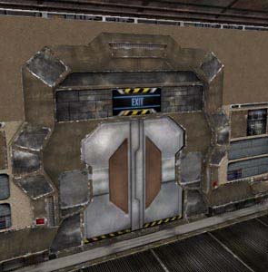
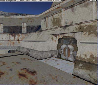
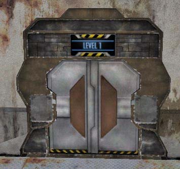
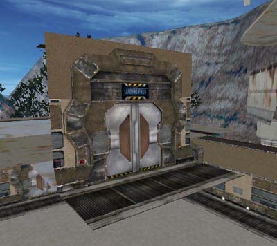
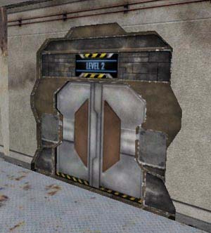
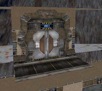
\...\Meshes\Equipment\ - equipment models e.g. ammo, cigarettes, weapons, etc, \...\Meshes\Implants\ - implants used by Logan (game main character), \...\Meshes\Inside\ - interior furnishing objects e.g. lamps, computer screens, all kinds of push
buttons, terminals; additionally, in subdirectory \...\Inside\Screens\ there are objects used for displaying all sorts of information e.g. on computer screens, above the doors etc,
\...\Meshes\Logan\ - well, this subdirectory is self-explanatory , it contains models of the main
character Logan and all the models of his hand weapons etc.,
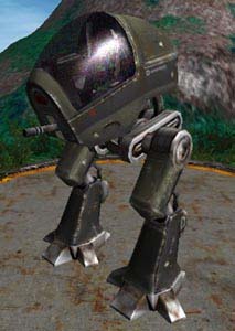
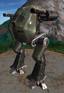
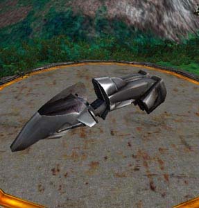
\...\Meshes\Movies\ - objects used in movies, \...\Meshes\Mp\ - multiplayer characters models, \...\Meshes\Naturals\ - models of trees, bushes etc, \...\Meshes\Objects\ - all kinds of barrels, grates, containers, etc, \...\Meshes\Sky\ - sky models, \...\Meshes\Vehicles\ - vehicle models used by player (mean of transportations) and static
objects (without interaction).
Let's get back to directory \Data\:
\Data\Panel\ - subdirectory with game fonts, \Data\Profiles\ - subdirectory with multiplayer profiles (settings, etc), \Data\Sounds\ - subdirectory with all sounds and music heard in the Chrome game, \Data\Textures\ - subdirectory with all textures used by the Chrome game (e.g. grass textures,
explosion textures, etc.).
3 Additionally, there are several directories concerning Java language:
\Java\ \JavaChromeEngine\ \JavaChromeGame\ \Jre\
The Chrome game uses Java language developed by Sun. the whole logics of the game
and the engine is based on Java language. It is a very convenient solution that enables easy to extend the game itself (so called mods). Java language is fairly easy to learn and there is a vast selection of documentation. If you are going to modify the Chrome game there's no better choice then using Java language. For sure, it is much easier then C++ (the Chrome Engine was written in C++). Since the main purpose of this document is to teach you how to create maps for the Chrome game and not modifying the game itself, I just add that on your maps you will use Java classes created by the Chrome game programmers. Class is a term related to object programming e.g. in C++ or Java. It is a set of logical connected data and functions designed for realization a certain task. With the ChromEd editor you will be able to assign objects to classes and also to change attributes of those classes e.g. assigning a vehicle to the Jeep class you can enable this vehicle for the player to drive.
There's one directory left: \Plugins\. In this directory there are various sort of the
ChromEd editor plug-ins. The ChromEd editor has an open structure which means that you can enhance its capabilities by different kind of add-ons (so called plug-ins). During your work you will also use several plug-ins created by the ChromEd editor authors.
This is proximally the whole content of the Chrome game directory. If during your
work you need anything from the appropriate directory I will point out where the needed element is located. At the very beginning I suggest creating a subdirectory \MyMap\ in \Data\LevelsNet\ that will contain everything that concerns the exemplary map created in this document. The map itself will be also named MyMap . Of course, if you were about to create a singleiplayer map then the subdirectory \MyMap\ would be created in \Data\Levels\.
Chapter 2 ChromEd editor basics 2.1 About ChromEd editor
At the very beginning I'd like to say what the ChromEd editor is. Shortly, it's the
editor which gives you the possibility to create maps for the Chrome game. Basically, word `map' has a colloquial meaning, more technical term would be `level'. But it is common to say `I make maps for Half-Life' so in this document I'm gonna use term `map' (not `level').
Not everything can be done in the ChromEd editor. As I wrote in Chapter 1 you will
need additional software, particularly graphics processing (in this document Adobe Photoshop 7 is being used) to create the terrain outline of the future map (more: in chapter about terrain creation). Then what is the ChromEd editor for? To put all the elements together into one coherent form. In the ChromEd editor you will generate the terrain on the basis of earlier prepared height map (in graphics processing program), in the editor you will overlay the color map (more info on this you can find in chapter about terrain creation in section about height map and about color map. Using the ChromEd editor you will generate vegetation (trees, bushes, grass, etc.) on your map, set up various objects (e.g. buildings). You may also do much more things like:
4 - define basic map parameters (sun position, terrain size), - assign proper Java classes to objects and also define their attributes (I wrote about Chrome
game using Java language at the end of chapter about the Chrome game; simply said, to let tree be a tree you need to assign an object representing a tree to the appropriate Java class etc.
- generate the terrain and object light map (the terrain light map is described in chapter
about terrain creation in section about light maps and the object light map is described in chapter about objects in section about object attributes),
- design patrol routes (so called waypoints) for AI an other objects (more info about
waypoints in chapter about singleplayer game in section about patrol routes),
- create cameras and define its movement path (in few words you will act as a director ) to
create the Chrome Engine movies for your maps, basically it will come handy only for singleplayer maps.
As you can see the ChromEd editor has a vast use, although I haven't mentioned all of
them yet. As I wrote in Chapter 1, the ChromEd editor has an open structure meaning that you can enhance its capabilities by using plug-ins (same as in other graphics processing programs like Adobe Photoshop, 3D Studio MAC etc). Along with the ChromEd editor you are getting several plug-ins e.g. for vegetation creation, making movies, AI controlling or even object inserting. All this is realized by plug-ins.
During composing this document programmers developing the ChromEd editor were
enhancing and adding new functions and plug-ins. Every time, when a new version of the ChromEd editor came up I tried to update this document. However, I decided to leave some paragraphs describing how to avoid certain errors and problems in older versions of the ChromEd editor. Thanks to that, if you spot a similar bug you will know how to solve the problem.
2.2 ChromEd editor file types
During your work with the ChromEd editor you will use files of the following types:
1. Bitmaps:
- .jpg - .png - .tga You can use bitmaps of 8 or 24 bits of color depth. Type .png file will be used by height maps, color maps, textures etc, .tga files mainly during light map generation. During my work I practically didn't use .jpg files.
2. 3D objects:
- .3da All objects in the Chrome game were created in 3D Studio MAX and exported to .3da format by a special plug-in. Alongside with the game and editor you are getting plenty of ready to use 3D objects (trees, rocks, buildings, walls, etc.) that you may use on your map. But you won't create the 3D objects by yourself (at most, you will put objects together e.g. building interiors),
3. Sounds:
- .wav, - .ogg, Music and other sound like water, trees noise, wind or conversations have to be of standard format .wav or .ogg. Because of large volume of .wav file it is advised to save
5 music in .ogg format. In this document I won't create any sounds. Basic effects as water or tree noise are built in the ChromEd editor and you can use them on your own maps.
The ChromEd editor itself generates various sorts of file types like:
- .map format of the map, - .bak, .ba1, .ba2, .ba3 formats of the backup copies of the map; every now and then
the ChromEd editor itself creates the backup copy (for safety reasons e.g. if, by mistake, you save he map with unwanted settings you can restore the previous version from the .ba1, .ba2,. ba3 files simply by changing the file extension from .ba1, .ba2,. ba3 to .map),
- .colmap format of the 3D objects collision map, - .pfm format of the AI collision (AI is controlled by computer, more about that in
chapter about singleplayer game in section about AI collisions,
- .fd2 format of the vegetation layers data, - .eds format of object selection group files, - .edcs format of class selection group files, - .lmap format of object light maps, - .cam format of exported camera files, - .fdk format of data key files (concerns making movies)
Those are the most important and most frequently used format files of the ChromEd
editor. If it's necessary I will describe how to save a file in a given format.
2.3 ChromEd editor interface
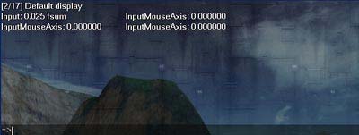
It's time to start describing the ChromEd editor itself an each of its elements. After the
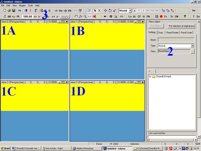
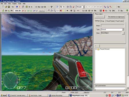
initialization a familiar (of course, not for everyone) screen will welcome you. Why familiar? At first sight the ChromEd editor resembles all kinds of 3D graphics processing programs (e.g. 3D Studio MAX):
6
This is the ChromEd editor after the initialization. As you can see it is divided into three
sections:
- 1A, 1B, 1C, 1D four view windows (viewports); here the map is displayed, in this
very windows you will place objects etc.; only one viewport may be active at the time and it is blue outlined,
- 2 active plug-in window, usually after the ChromEd editor initialization Mesh
Browser plugin is active (this plug-in is responsible for placing objects, more info in chapter about objects), NOTE: not every plug-in displays in this place,
- 3 the ChromEd editor tool bar (with editor main menu above), on the tool bar there
are various icons activating proper plug-ins, tool allowing to work on 3D views (e.g. rotate and translate the camera), individual tool bar elements will be described in this chapter.
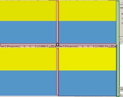
To start I will characterize viewports and their functions. Viewports are separated by
the splitter that enables altering the proportions of their sizes:
7
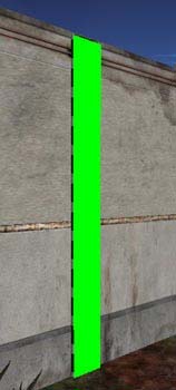
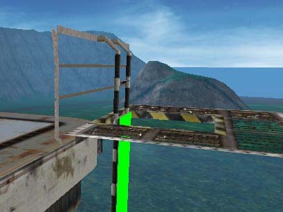
On the picture above I red marked the splitters modifying viewport vertical and
horizontal size (upon pointing with mouse cursor that splitter the cursor changes its shape that informs you in which direction you can alter the viewport size; you need to press and hold left mouse button and move the cursor in required direction). I black marked the splitter enabling altering the viewport in all four directions (the same one viewport increases its size in two directions and the others decrease). I green marked (to the right of the viewports) the splitter enabling altering the plug-in window size (the same increasing or decreasing the size of viewports). Try on your own and you gonna see that altering the viewport size is quite simple. Additionally, each preview may be minimized, maximized or closed:
The base of work is like every other Windows application. There's a concept relating
viewports to observers, i.e. objects combined with camera. What is the use of observers? Most of all without an observer you wouldn't be able to see your map in the viewports. The observer may act like a sort of a tab. If your map is large enough then transition from one place to another may take a while. By creating observers in proper points you can quickly switch between them and `be' in other places at once. By default there are four observers, one in each of the viewports. To set an additional observer you have to translate the camera in active viewport to the required point (how to translate the camera is described below), then right click in this viewport. A context menu opens. Choose Observers -> Set observer:
8
`Set observer' window appears. You have to name the observer e.g. Forest (this way you will know at once that the observer is placed above the forest) and the X, Y, Z positions of the observer. Since those will be parameters from the current camera position leave it without changing and click OK:
By default, the first four observers are named: view0, view1, view2 and view3. Each viewport may be linked with one of many observers and you may switch between them by choosing Observers -> Switch to:
In `Observer' menu, besides the `Set observer' and `Switch to', following commands are available:
9
Selecting `New' you may create a new observer.
NOTE: This command may only be executed if you close the viewport. To open a new viewport you can select Observers -> New. It is also significant that closing the viewport removes the current observer! Duplicate command enables you to copy the current observer. Hide command hides the current observer. Close command closes the observer (and the same closes the viewport). Basically, Close is very similar to Hide. Close All closes all observers. Using `Near clipping plane' you may set up to what distance the observer will display the map:
In Near field type the distance (100 units = 1m) and click OK. `Near clipping plane' is being used very rarely, that's why I suggest leaving the default value (10). Next command `Far clipping plane' enables you to set till what distance the observer will display the map (the same here, 100 units = 1m). This option may be useful while displaying real big maps. This way, if you don't want to overburden the ChromEd editor too much you may decrease the distance up to the map will be displayed (the same the ChromEd editor won't have to display the whole map. The `Far clipping plane' window is similar to the `Near clipping plane'. In Far field type the required value and click OK. The default value is 50000. Now choose Speed factor. The `Observer speed factors' window opens:
10 There, using the slide bars set the observer camera rotation speed (`Rotate') and movement speed (`Move'). By doing this you may speed up (down) the camera movement in the viewport or speed up (down) the camera rotation speed. After setting the required values close `Observers speed factors'.
This is, more less, how the work with observers looks like. Unfortunately, the observers functions do not work properly . You cannot create more then four observers and then switch to them! I must admit, however, that during my work with the ChromEd editor this fact didn't bother me at all. The four default observers, available after the editor initialization is just enough. Right click once again one of the portviews:
As you can see other commands are available. Assign movie enables you to assign the move making camera to the viewport, and Detach movie detaches the camera. Choose View aspect and the View Aspect window opens:
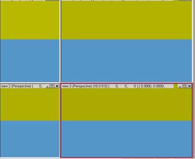
Using this function you may resize the active portview. In `Aspect [width : height]' fields type width-height ratio (as you can see on the picture it is 16:9) and in `Initial width' field give the portview initial width. Then click OK. This is the look of the ChromEd editor with parameters as on the picture above: 16:9, 500:
11
I red marked the aspect of the portview (16:9, 500). If you set the aspect then altering size of the portviews function (by using the splitters) won't work. If you want to alter the portview size you need to turn the aspect off. Right click in one of the portviews and check out View aspect (currently this command is checked; in fact, it's not a command but option but since it's available in menu I take it as a command):
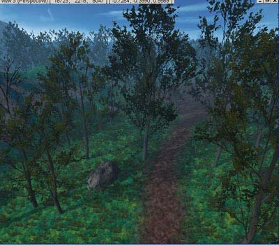
Right clicking on the portview info bar gives you an additional command, namely you can switch observer camera to the different views of your map:
12
- Perspective perspective view (3D), - User orthogonal (upright) user view, - Front front orthogonal view, - Back back orthogonal view, - Top top orthogonal view, - Bottom bottom orthogonal view, - Left left side orthogonal view, - Right right side orthogonal view,
If you choose e.g. Top view and then rotate the observer camera then the view will automatically switch to the User view. It is because only the User view is a 3D view and all the others are not and they do not handle camera rotation (only zooming in and out)!
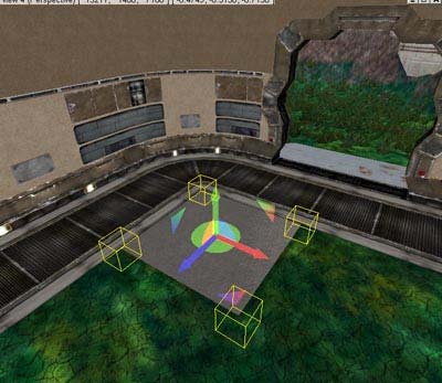
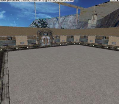
On each portview info bar other important data are displayed:
Starting from left:
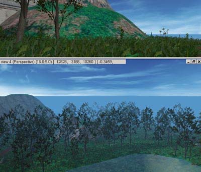
- observer name, on this example it's view3, - observers view mode (in brackets), in this example it is Perspective mode, - current X, Y, Z position (calculated from the beginning of your map) of the observer
camera (in square brackets), in this example it's position: X = 12443, Y = 1477, Z = 14138 [ 12443, 1477, 14138 ],
- observer camera direction (also in square brackets), in this example it is position:
- 0.6294, 0.0197, -0.7768 [ -0.6294, 0.0197, -0.7768 ].
In addition, if the movie making camera is assigned to the portview the `Movie' caption is displayed next to the observer view mode:
Those are all the necessary information about the portviews.
13
In the end, I just say that during my experience I found the perspective view most useful, so right after the ChromEd editor initialization I always maximized the perspective view and, basically, I only worked using this view (because of the ease of object camera maneuvering in this view).
I think you're done with portviews by now . Let me explain now the ChromEd editor
tool bar. Most of the available tools from the tool bar are from the proper plug-ins e.g. observer camera rotation is from Mesh Browser plug-in (which is described more precisely in chapter about objects in section about object adding), but because of certain integrity of those tool with the tool bar I will describe each icon here, although more detailed information you can find in following chapters and sections of this document. Besides the short description of the icon I also mention the key shortcut, if one exists. It's a default shortcut designed by the ChromEd editor authors. If you want to change the shortcut choose Tools-> Shortcuts:
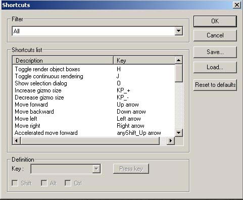
The Shortcut window opens:
From `Filter' list you may select the ChromEd editor element shortcuts you want to display. Following elements are available: - `All' all the ChromEd editor shortcuts (I suggest selecting this option for changing the shortcut), - `Editor' only the editing relating shortcuts, - `Control' observer camera movement shortcuts,
14 - Environment Enviroment plug-in shortcut, - `Films' Film plug-in shortcuts, - Forest Forest plug-in shortcuts, - `LightmapsEd' LightmapsEd shortcuts; NOTE: currently this plug-in is integrated with
Environment plug-in and doesn't have its own icon on the tool bar,
- `StringsEd' StringsEd plug-in shortcut; in the further parts of this document I will use the
term `strings editor' instead of `StringEd plug-in',
- `TerrainEd' TerrainEd plug-in shortcuts.
Great! If you want to change the shortcut you find its description on the `Shortcut list' list and select it (in example I selected the shortcut for selecting objects window):
Now, in the Definition panel you may assign a new shortcut. To do that, select the required letter from the Key list:
In addition, you may select the control key you want to use for required shortcut (SHIFT, ALT and CTRL). You may use all three keys all together by any means . Another way to change the shortcut is to click Press Key button and then pressing the proper key combo e.g. CTRL + O. There are several buttons right to the Shortcut window:
Clicking the Reset To Defaults button restores default shortcut setting (designed by the ChromEd editor authors ). Clicking Save you may save your shortcut setting (in .sdat format file). Clicking `Load' you may load your shortcut setting (from .sdat format file). To confirm the new shortcuts click OK.
Since you already know how to change the shortcuts let me describe each of the tool bar icons:
15 CTRL + N
New map (Create a brand new map)
CTRL + O
Open the map
CTRL + S
Quick save the map
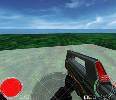
Game mode, in few words you may test your map from the game perspective . Pressing the ALT-F4 you leave the game mode. Attention! Before entering the game mode I strongly suggest saving the map by pressing CTRL+S!
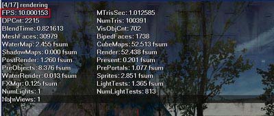
Rendering options. More info in section about rendering options.
Error list of the map. If an error appears on your map then this icon will flash. Then you may click this icon and find out more about that error. More info in section about errors.
O
Show
selection
dialog
Object selection window. It enables you to search and select objects and events on your map. More info in section about object selecting.
Selected object attributes window. More info in section about object attributers.
Object reference window. More info in chapter about singleplayer game in section about declaration of variables.
16
Object grouping window. More info in chapter about objects in section about object grouping.
Hide the selected objects. After selecting an object (or objects) and clicking this icon you may hide this object. It will be invisible but it won't be removed form your map.
Hide all unselected objects. If you selected an object and click this icon then the rest of the objects will be hidden. Of course, if you didn't select any object then all the objects on the map will be hidden. NOTE: If you click this icon (hide all objects) the Environment (or any other) plug-in will be unavailable (the attribute window will open but no tab or attribute will be available) and the same you won't be able to change any of the map settings etc. It is because the map you are creating also is an object and you just hid all the objects. In such case you have to either unhide all objects (using the proper icon) or select the map object (map object name is LEVEL) in object selection window.
Unhide objects. Using this icon you may unhide a single object. To unhide an object and make it appear on your map you have to open the object selection window (described in chapter about objects insectionaboutobjectselecing). Find the object on the list and then click this icon.
Unhide all objects. If you want to unhide only certain objects not all you have to use the object selection window and the single object unhide list.
Collapsing (combining) window. Do not mistake with grouping! Using this window you may combine several objects into one big object. More info in chapter about objects in section about object collapsing.
Mesh Browser plug-in (described in chapter about in section about object adding). Using this plug-in you may add objects or events (e.g. movies, dialogues, patrol waypoints etc.) to your map.
17
S
Set select object mode
Select object mode. To select an object simply left click it. In addition, if you select an object and press `X' key then the observer camera of the active viewport will be centered on this object. Pressing SHIFT+X causes the observer cameras in all viewports to be centered on the selected object. You may select several objects at once using the standard Windows OS way click and hold left mouse button and select the area with required objects. You may add new objects to those already selected. Press and hold CTRL and click the required object.
SPACE
Toggle locked selection mode
Toggle locked selection mode. If you selected an object and locked selection (by pressing SPACE or clicking the icon) then you cannot select any other object. It is a good habit that after selecting an object you lock the selection. It guaranties you that you won't unselect this object by mistake. Pressing SPACE again (or clicking the icon again) you turn locked selection off.
ALT + M
Set move objects mode
Move object mode. Left click and hold the object you want to move and then move the mouse in required direction. You may move several objects at once (you need to select them before). NOTE: If you want to move several selected objects in the same direction then you have to set the axis coordination mode to `Word'. The axis coordination mode is set in the list on the tool bar:
If you don't do this it may happen that each of the selected objects will move in a different direction. Why is that? If the axis coordination mode is set to `Word' then all the object operations (movement, rotation, scaling etc.) are related to the map terrain where X, Y, and Z axes do not change! In `Local' axis coordination mode all the operations (movement, rotation, scaling etc.) are related to the selected object, not the map terrain. Please, remember that! But before you move the selected object you have to choose the axis to move. Use the icons:
.
R
Set rotate objects mode
Rotate objects mode. Left click and hold the object to rotate and move the mouse in the direction. You may rotate several objects at the time (selecting them before). Please, remember about selecting the proper axis coordination mode and the axis you want to rotate the object around.
18
Object scaling mode. Left click and hold the object to rotate and move the mouse in any direction. You may scale several objects at the time (selecting them before). Please, remember about selecting the proper axis coordination mode and the axis you want to scale the object by.
Attach an object to the object hierarchy. Having an object selected, click this icon and than click the object you want to attach the selected object to. The attached object becomes the `child' and the attaching object becomes the `parent'. Please remember, that moving the `parent' object will also cause the `child' object to move. This way you may make your life easier e.g. attach the light object to the lamp object. From now on whenever you displace the lamp you automatically displace the light as well. Using the attribute window you may find out if the given object is attached to the hierarchy. If yes, then in `Parent' field there is the `parent' object name:
Detach object form the hierarchy. Having selected object in the hierarchy, click this icon. You can also detach objects from the hierarchy using the object attributes window. To do that click `X' next to the `Parent' field:
ALT + S
Toggle object snap mode. NOTE: This mode may slightly differ while activating by the icon from activating by the shortcut (ALT + S). Using the shortcut you go directly to the object snap mode. Snap is used during creating e.g. buildings (more info in chapter about objects in section about buildings). Thanks to that function one object is automatically attracted to another. Press ALT + S again to turn snap mode off. Turning the snap mode on by using the icon opens `Snap Properties' window:
19
In `Connection distance' filed give the distance at which one object will attract another. I suggest not altering the value (50). Then click OK and you are in snap mode. Click the icon or press ALT + S to turn the snap mode off. If you want to change the snap mode settings click again the snap mode icon.
Strings Editor (SrtingsEd). This editor contains all the phrases from the Chrome game. More about this editor and the strings you can find in chapter about singleplayer game in section about dialogs.
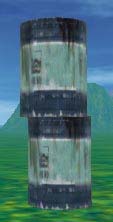
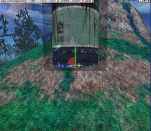
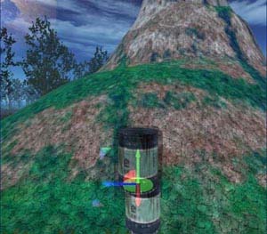
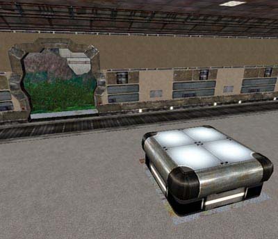
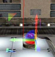
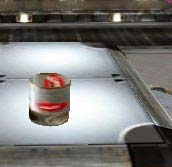
Align selected object to the terrain in relation to the object axis. The object is aligned vertical down while no other objects are concerned so it may happen that one object will penetrate the other (if the other is in the way of the first one). For example, if you have a barrel (the pivot point of Beczka.3da object is located in the center of its base, more info about the starting point in chapter about objects in section about the Gizmo), that `hangs in air' and is angled to the terrain then clicking the icon will cause aligning the barrel without changing it angle to the terrain (so a part of the barrel will dig in into the terrain):
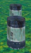
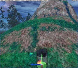
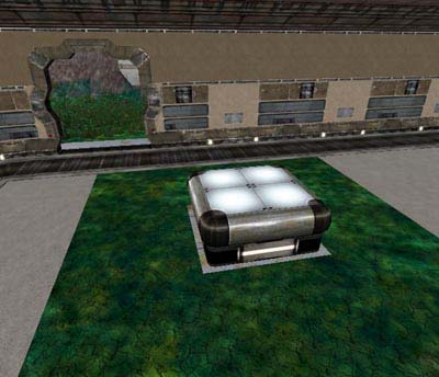
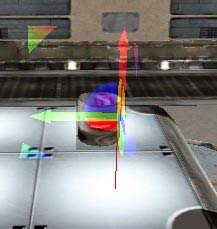
Align selected object on the terrain in relation to terrain axis (not object axis!). The object is aligned vertical down while no other objects are concerned so it may happen that one object will penetrate the other (if the other is in the way of the first one). Back to the barrel example. The barrel is in the air angled to the ground. Clicking the icon will cause aligning the barrel to the terrain and leveling it relative to the terrain (so it won't be dug in into the terrain):
20
A
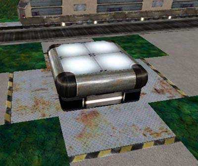
Toggle alignment mode for selected object to the terrain or other objects. Select the object to align, turn alignment mode on and click the place on the terrain you want to place it. You may also click another object, meaning that the selected object will be aligned the other object (it will be located one on another):
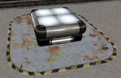
Toggle alignment mode for selected object on the terrain. Select the object to align, turn alignment mode on and click the place on the terrain you want to align it to. You may also click another object but the selected object won't be placed on that object (like in alignment mode mentioned above) but will be placed in the closest empty space close to the object:
21 Using these icons you may place objects on other objects (not terrain) more precisely e.g. to move the painting closer to the wall. More about these icons in chapter about in section about building interiors.
ALT + P
Set pan observer mode
Observer camera movement mode (up, down, left, right) of the active viewport. Left click and hold and move in required direction. To move the observer camera you may also use HOME key. It enables you to switch on the observer camera movement mode without exiting the other action mode e.g. objects rotation. To do so,press and hold HOME key and left click and hold in the active portview. Now move the mouse in the required direction. Finally by releasing HOME key and left mouse button you go back to the previous action mode. You may also directly move the observer camera using the middle mouse button (providing you have a three button mouse) and also by using the cursor keys (left, right). You may accelerate the camera movement by pressing and holding SHIFT key.
ALT + R
Set rotate observer mode
Observer camera rotation mode of the active viewport. Left click and hold in the active viewport and then move the mouse in the required direction. For the observer camera rotation you may also use PAGE DOWN key. It enables you to switch on the observer camera rotation mode without exiting the other action mode e.g. objects movement. To do so,press and hold PAGE DOWN key and left click and hold in the active portview. Now move the mouse in the required direction. Finally by releasing PAGE DOWN key and left mouse button you go back to the previous action mode.
ALT + Z
Set zoom observer mode
Observer camera zoom in/out mode of the active viewport. Left click and hold in the active viewport and then move the mouse in the required direction. For the observer camera zoom in/out you may also use PAGE UP key. It enables you to switch on the observer camera zoom in/out mode without exiting the other action mode e.g. objects movement. To do so,press and hold PAGE UP key and left click and hold in the active portview. Now move the mouse in the required direction. Finally by releasing PAGE UP key and left mouse button you go back to the previous action mode. You may also directly zoom in/out the observer camera using the mouse wheel (providing you have a mouse with the wheel) and also by using the cursor keys (up, down). You may accelerate the camera zoom in/out by pressing and holding SHIFT key.
ALT + O
Set orbit observer mode
Observer camera orbiting mode around the selected object in the active portview. Left click and hold in the active viewport and then move the mouse in the required direction. For the observer camera orbiting you may also use END key. It enables you to switch on the observer camera orbiting mode without exiting the other action mode e.g. objects movement. To do so,press and hold END key and left click and hold in the active portview. Now move the
22
mouse in the required direction. Finally by releasing END key and left mouse button you go back to the previous action mode.
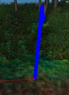
Observer camera orbiting mode around the current central point in the active portview. To find out the location of current central pint click the icon:
To orbit the observer camera around this point left click and hold in the active portview and move in the required direction.
G
Change observer mode
Observer camera observe mode in the active portview. NOTE: This mode may slightly differ while activating by the icon from activating by the shortcut (G). Using the shortcut you go directly to the observe mode. While in this mode you move the observer camera by cursor keys (pressing and holding SHIFT key accelerates the movement), rotate by using the mouse (as if you played with the ball). You may also use the middle mouse button and the mouse wheel providing that you have one . Click the icon or press G to turn the observe mode off. Turning the observe mode on by using the icon opens the Observer Mode Properties window:
You may set the observer camera move ratio (forward, backward in `Move ratio' field, and left, right in `Pan ratio' field. You may also define the acceleration you will gain by pressing and holding SHIFT while camera move (`Speed factor' field). Additionally, you may set the camera height over the terrain (`Camera Height' filed in `Constant Height Mode' panel). By checking the `Constant Height Mode' box in `Constant Height Mode' panel) you make the observer camera to be in the specific height above the map. The same the camera movement will correspondent the terrain shape below (you won't be able to increase or decrease the observer camera height). Finally click OK. Now you're in observe mode. Press G to turn this mode off. If you want to change the observe mode settings click again the observe mode icon..
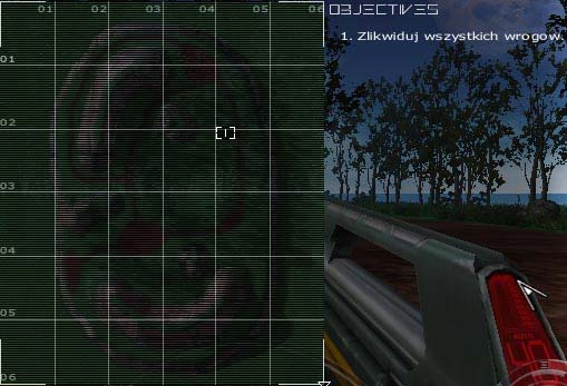
23
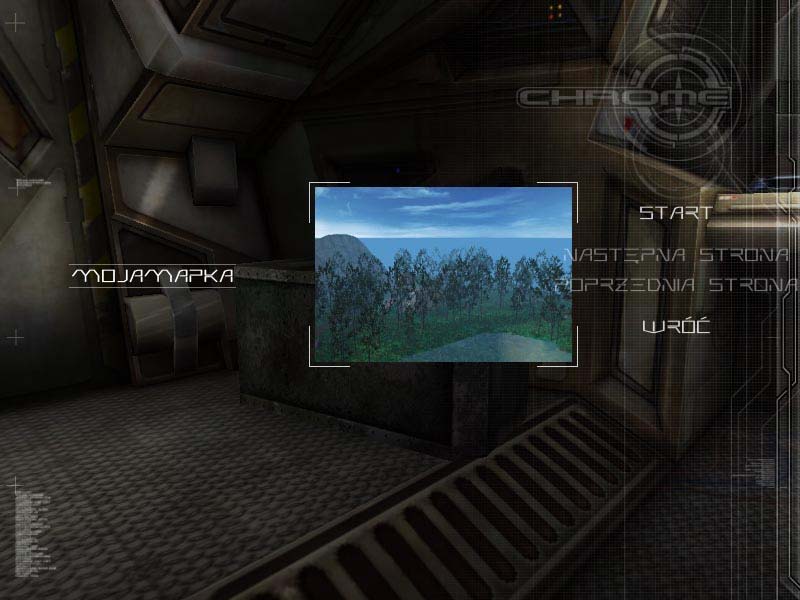
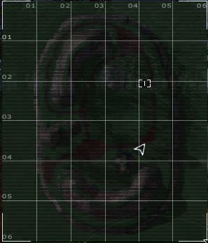
Satellite picture of the map. This is the same picture as the minimap picture (`M' key) in the Chrome game. More info in chapter about terrain creation in section about minimap.
Save the screenshot of the current active portview. Clicking this icon opens `Take screenshot' window:
Click the dots button next to the `Bitmap' field and type the file name you want to save the screenshot (the screens hot will be saved in .tga format). Set the resolution of the saved screenshot in `Width' and "Height' fields. I suggest 800x600 or 1024x768. Finally click OK. Unfortunately, this function doesn't work properly or even crashes the ChromEd editor, that's why it is advised not to use this function to take screenshots (which, by the way, are quite useless)
C
Set count distance mode
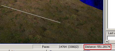
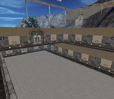
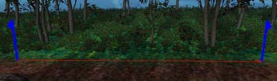
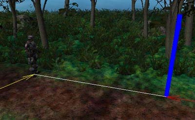
Using this icon you may measure up the distance between two points. Left click and hold in the active viewport and then draw the line from one point to another. The distance between the two points is displayed at the bottom of the ChromEd editor in `Distance' field:
Please remember that 100 units = 1 m, so on the example above the distance between the two points is approx.5.5 m.
24
Environment plug-in initialization. It's one of the most important plug-ins in the ChromEd editor. You begin your map creation with the Environment plug-in. It is described in chapter about terrain creation in section where you use this plug-in.
Collision map generator for the objects controlled by computer (AI). The collision map is described in chapter about singleplayer game in section about AI collision map.
Objects identifiers (ID) renumbering. I suggest not using this function because it is not 100% error proof , even more its malfunction might cause a great loss in some cases you would have to start creating your map from the beginning! Click the icon in extreme, more exactly in the moment you notice that the map objects have the save IDs (IDs are described in chapter about objects in section about object selection). In addition, after using this function you need to regenerate the object lightmaps (lightmaps are described in chapter about objects in section about object attributes). After clicking the icon the Hierarchy Check window opens with the information that lightmap regeneration will be necessary:
Clicking YES you renumber all ID objects on the map. Just don't forget to regenerate the lightmaps.
Height map generation by the ChromEd editor. Using this function you may generate a new height map. More info on this subject you may find in chapter about terrain creation in section about terrain modifying (the Terrain plug-in will be used).
Height map generation for rain and snow effects (and other effects of that sort). This map is generated mainly not to let the rain to fall inside the buildings. During the generation of this map all objects on the map are considered therefore it should be generated at the very end when every single object is already placed on the map. More info on this subject you may find in chapter about event creation in section about rain and snow.
25
Films plug-in initialization. Using this plug-in you will create movies for you map (on condition it's a singleplayer map). During the work with the plug-in you will use icons:
I explain them while describing the `Films' plug-in.
Forest plug-in initialization. Using this plug-in you will generate the vegetation on your map . More details in section about nature.
Terrain plug-in initialization. Using this plug-in you will modify the map terrain. This plug-in is described in chapter about terrain creation in section about terrain modification.
Height map generation (in .height format). This file type are much more detailed then height map based on bitmaps. While modifying the terrain with Terrain plug-in .height files are used. More about this in chapter about terrain in section about terrain modifying.
All shortcut use right ALT key. Of course, if a given shortcut requires ALT key at all. Left ALT is not used simply because it is a integral part of the ChromeED work.
By now you should have a general idea how to operate the ChromEd editor, how to
modify the object position etc. If later on, any menu command will be necessary I just describe it.
2.4 Rendering options
Clicking the icon
opens the Rendering options window. In time, the map you
build will contain more and more objects, plants, etc. therefore the work with the map will be more complicated. Why is that? ChromEd editor will process more and more objects which may obstruct camera rotation or translation. There is, however, a way to prevent that by using the rendering options. Rendering options window:
26
These options enable to turn on/off rendering of the chosen elements on your map. Thanks to that Chrome Ed editor doesn't have to process objects turned off from rendering, which will accelerate the editor's work. For example, you can turn off sky rendering. In the game itself the sky is a significant feature but during the building of the map it isn't, is it? So, you can temporary turn sky rendering off. Here is description of each option: Terrain:
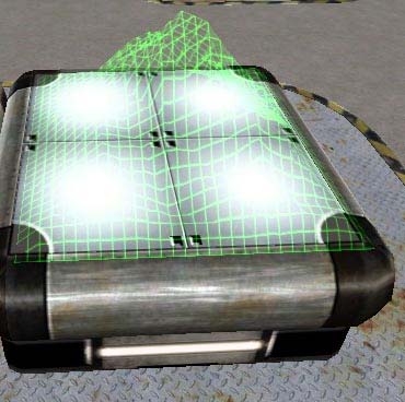
Checking `Rendering' option turns on rendering of the terrain on your map, unchecking turns that off. If, additionally, you check `Wireframe' (providing that `Rendering' option is checked), only the terrain grid of the map will be displayed (option not available in older version of ChremoEd) Horizon:
27 Checking `Rendering' option turns on rendering oft the horizon on your map and unchecking turns that off. Sky:
Checking `Rendering' option turns on rendering of the sky on your map and unchecking turns that off. Trees:
Checking `Rendering' option turns on rendering of the trees on your map and unchecking turns that off (trees that had been generated by Forest plug-in described in chapter about nature). If, additionally, you check `Wireframe' (providing that you checked `Rendering' option before), only tree grid will be displayed (option not available in older version of ChremoEd). Water:
Checking `Rendering' option turns on rendering of the water on your map and unchecking turns that off. Grass:
Checking `Rendering' option turns on rendering of the grass on your map and unchecking turns that off (grass that had been generated by Forest plug-in described in chapter about nature ). Fog:
Checking `Rendering' option turns on rendering of the fog on your map and unchecking turns that off. Attributes visualization:
Checking `Rendering' option turns on rendering of the fog on your map and unchecking turns that off. This option enables you to display e.g. lines between patrol checkpoints or connection lines between AI and the patrol checkpoints etc.
28
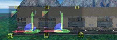
Options relating rendering objects are grouped separately:
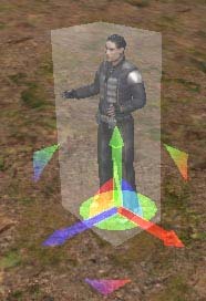
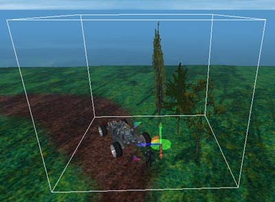
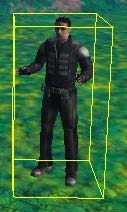
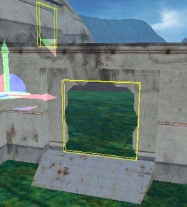
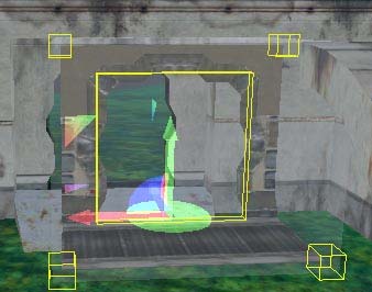
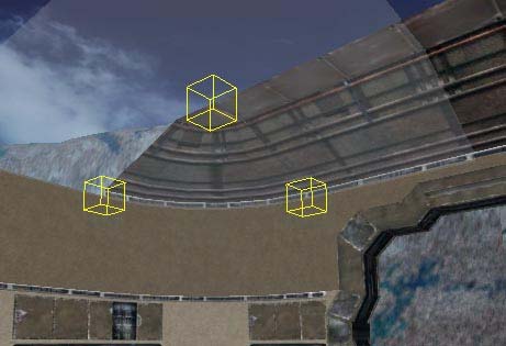
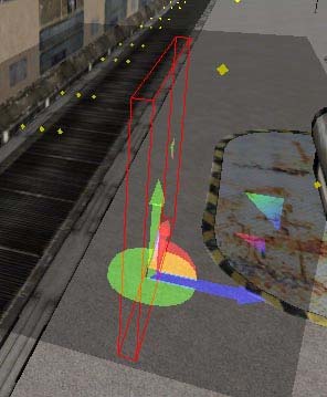
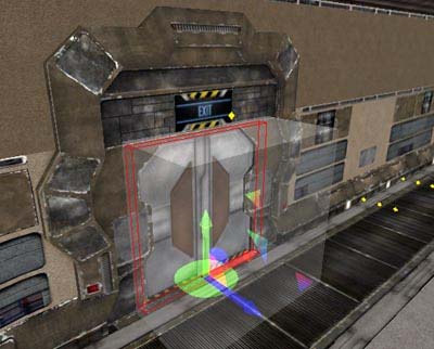
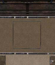
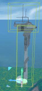
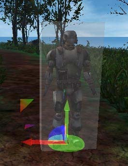
Checking `Rendering' option in the All panel enables you to turn on rendering objects on you map (buildings, vehicles, etc.) and unchecking turns that off. Additionally, if `Rendering objects selection boxes' is checked, the extents will be displayed around marked object. An extent is a white, transparent box visible around marked object:
These extents basically do not mater. They inform you about the given object size. Additionally, by pressing `H' key you can turn on/off displaying off extents on marked objects:
29
You can also choose rendering mode in `Rendering mode' panel:
- `All' the whole objects are rendered, - `Wireframe' only the objects grid is (option not available in older version of ChremoEd), - `Extents only' only the objects extents are rendered.
Also you may turn on/off rendering objects of a given class in `Object classes excluded from rendering':
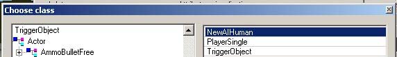
If you want e.g. not to render objects controlled by computer (AI) click the button `Add'. Then, in `Choose class' window select object class that won't be rendered on your map:
In this example it is NewAIHuman class. Click OK in `Choose class' window. After selecting the proper class, click OK in `Rendering options' window. From now on all objects of NewAIHuman class will not be rendered on your map. Of course, if you want to restore rendering of these objects, mark the proper class on the list `Object classes excluded from rendering' and then click `Remove'. There are three options at the bottom of `Rendering options' window:
30
Here, you can turn on/off rendering of the following elements:
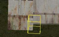
- `Control: Render hooks' objects that can be connected (e.g. building walls) have
special attachment points hooks, which enable to put together these objects in appropriate positions to fit each other (more about that in section about buildings).
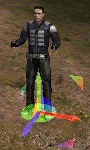
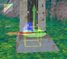
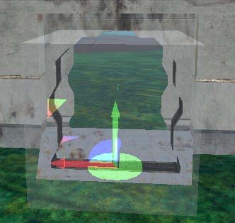
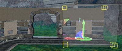
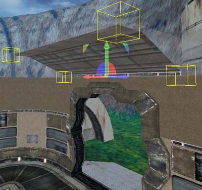
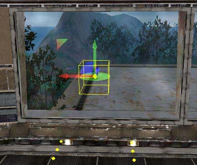
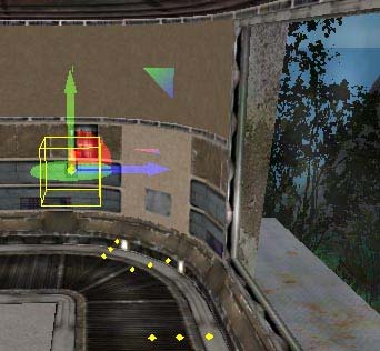
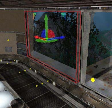
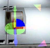
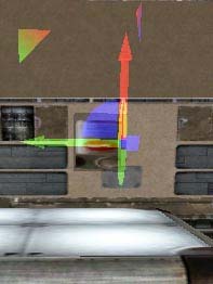
- `Control: Render the Gizmo and boxes during orbiting' enables to turn on/off the
Gizmo rendering (the Gizmo is a special tool to translate and rotate objects, more in section about the Gizmo) and extents during camera orbiting around an object (extents are mentioned above),
- `LightmapsEd: light ranges' enables to turn on/off rendering the light generated by
the lightmap.
If you noticed that during the work on your map e.g. camera rotation is more difficult
etc. (the more complex map is the more objects ChromEd editor will have to process, and the processing speed depends on your computer system performance) then you can turn off rendering of such objects as sky, fog or even water, grass and trees.
2.5 Errors
Clicking the icon
opens the Errors window, which displays all errors that turned up
on your map. The Errors window:
31
If on your map an error appears the flashing icon
will inform you about that. The errors
may come out during the ChromEd editor initialization, loading of the map or even working on the map. In Errors window the information about errors are displayed, e.g. a file or object class is missing (object classes are mentioned at the end of chapter about Chrome game). The Errors window has several tabs. Each tab informs you about an error from following categories:
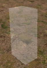
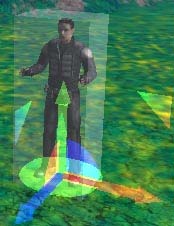
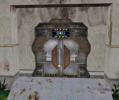
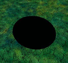
- Meshes tab displays the mesh list (mesh is a 3da file representing a 3D object) that
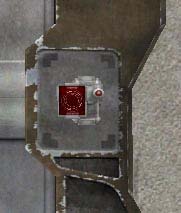
has not been loaded during the map loading process. All objects without a mesh will be, by default, replaced by a large red explanation sign:
so, if after loading of your map you see such a red exclamation sign it means that in this point was an object which mesh wasn't found,
- Critical Errors tab displays the critical error list that have a key meaning to proper
working of your map,
- Java Classes tab displays the error list related to Java classes, with options on this
tab you may display various errors related to Java classes:
- `missing java classes' option displays the list of missing Java classes, - `invalid java classes' option displays the list of invalid Java classes, - `objects using invalid java classes' option displays the list of objects that use
invalid Java. There are following options: `as object class' displays list of objects with invalid class and `as attribute class' displays the object list with invalid class attributes.
- Missing Java Attributes tab displays the error list related to invalid Java attributes,
this list may be sorted by following options:
- `sort by object name',
32 - `sort by object class',
- Last Action tab displays errors that appeared after the last operation; additionally, on
this tab there are buttons that make errors preview easier:
`|<' button jump to the beginning of the error list, `<' button scrolls the list backward, `>' buttons scrolls the list forward, `>|' jumps to the end of the list, additionally, you may save the error list to file by using `Dump to file' button.
That was the Errors window. When the Error window icon starts to flash I recommend
clicking it at once and checking where the error is. The ChromEd editor includes a certain error itself. If you load the map with en error (e.g. missing mesh) and you don't check what error it is but you load the next map then the Error window icon will still be flashing. If at this moment you click it you may cause ChromEd editor halt. During my experience with this editor, whenever I wanted to load another map I simply restarted editor. Maybe it is not the best solution but for sure it is the safe one !
After reading this chapter you should be quite familiar with basic rules of ChromEd
editor operating, so, I think, it's a high time to begin creating your first map!
Chapter 3 Terrain creation 3.1 A bit of theory
At first, a little bit of theory. I'd like to explain you terms of height map and color map
from a technical side. That is minimum information necessary required to comprehend rules of map creation to the Chrome game. Of course, if during the map creation any additional information is necessary I will try to explain it more in detail at once.
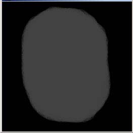
So, what is that height map and color map? Let's begin with the height map. Simply, it
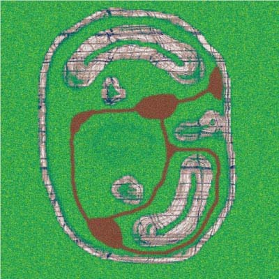
is just a bitmap containing terrain outline of the map. Only tints of grayness (and of course black and white) are used on this map. The height map has to be squared and its size (resolution) has to be a power of number 2. ChromEd Editor and Chrome engine require the height map size to be 1 pixel bigger vertical and horizontal. The example resolutions are: 257x257, 513x513, 1025x1025 or even 2049x2049 but I wouldn't recommend exceeding oven 1025x1025. I usually apply 257x257 resolution. The height map has to be an 8 bit color bitmap, meaning 255 tints of grayness and has to be in .png format file (one of the standard formats recognized by the Chrome game). To understand more exactly the way of height map creation, see the picture below:
33
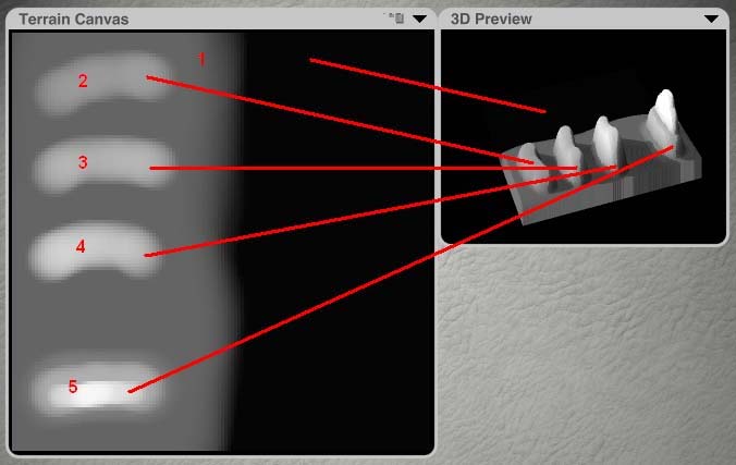
To the left (Terrain Canvas) there is the height map and to the right there is the terrain
preview (2D Preview) generated on the basis of this height map. This is the way the Chrome game generates the terrain by using the height map. On this picture I connected with red lines elements of the height map matching the generated terrain preview. It's easy to notice, black color generates nothing. While the black color gets lighter (becomes gray) the reliefs appear. The lighter tint is the relief is higher. In this way you can create hills, valleys, mountains etc. by overlaying one tint on another (see element nr 5) you may create more realistic mountains (not upright walls like elements 1 to 4). I think it`s quite understandable, isn't it?!
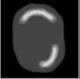
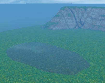
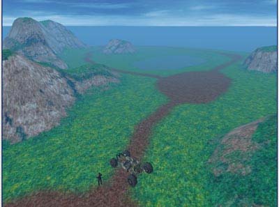
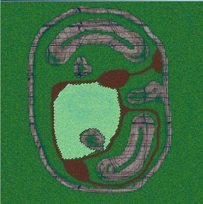
And there's a color map left. What is the color map? Please see the picture below:
So, the color map is just a bitmap presenting the terrain texture. Depending on what your map will present you will mark on the color map roads, river banks etc. You have to remember that the color map has to be squared and its size (resolution) has to be a power of number 2 either, but it doesn't have to be bigger by 1 pixel. The example resolutions are: 256x256, 512x512, 1024x1024, 2048x2048 or even 4096x4096!!! It is advised to generate the color map (this will be done by Corel Bryce program) in 4096x4096 resolution. The color map has to be an 8 or 24 bit color bitmap, by the way, it also concerns any other bitmap (e.g. texture map) used by
34 the Chrome game. The color map also has to be in .png format file. After the ChromEd editor generates the terrain by using the height map, the color map will be overlaid to create coherent, texturized terrain.
To create your map you need the detail map as well. It is also a bitmap but its size
(resolution) doesn't have to be that big. Its resolution may be only 64x64 pixels, 128x128, 256x256 and 512x512 resolutions are also in use. Please, remember that still it has to be a square bitmap of resolution of the power of number 2 and it doesn't need to be enlarged by 1 pixel. The detail map represents the terrain in micro scale - walking on your map the player, under his feet and around, will see exactly this detail map. This map will be overlaid on the color map and it will be duplicated an all over the terrain. This is the example detail map:
One map is left. It's so called lightmap. You will create (or rather the ChromEd editor
will do that for you) just when your map is 100% ready. This map simply contains objects shading e.g. trees, buildings. After being generated it will be overlaid on the color map, which will give the effect of object shadows on the ground. More: in section about lightmap.
I thing it's enough of theory and my explanation brought you closer to what it's all
about. Let's get to the practice which will enable you to comprehend and consolidate all this even more.
3.2 Height map
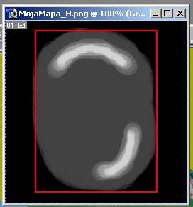
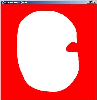
It is time to create your first height map. Start Photoshop program, choose File ->New:
Before you start creating a new map press `D' key (which sets black as default tool color and white as default background color) then press `X' key (which swaps colors, white is default tool color and black is default background color). Now choose File -> New. In the New field
35 put the name of the map. Basically, to the map name I add `_H' to point out it's gonna be a height map. Now set the resolution. In `Width' field put the map width. You need to remember that the height map has to be squared and its size (resolution) has to be a power of number 2 plus one pixel vertical and horizontal. Let's set its resolution to 257x257. Because the height map uses only the tints of grayness (and black and white) it's enough to choose `Grayscale' from the `Mode' list. Additionally, check `Background Color' option in the Contents panel that means your map will be filled with black (it's been set by `D' and `X' keys):
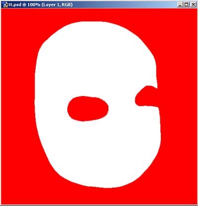
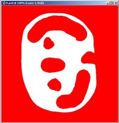
Most of the graphics programs, including Photoshop, enable to work with so called layers. This will make the work easier. Currently, the first layer is the black map. On the second layer create the island outline and on another layer mountains. On the bottom right side of Photoshop screen there's a small window with Layers tab containing small button `Create a new layer':
36 After clicking this button (which you are supposed to do) another layer will appear: Layer 1. Change the name to Island (you should double click the Layer 1 label). To the left of the layer name there should be a small brush which means that layer is active and it will be edited.
It is time to pain your island. On the left side of Photoshop screen there is a tool bar. Choose the Brush Tool:
Notice that on certain buttons there are small downward-pointing triangles (at the
bottom right corner) indicating that under those buttons additional functions are available. In case you don't see the brush icon, just select this triangle and the list of hidden tools will appear. Then select the Brush Tool.
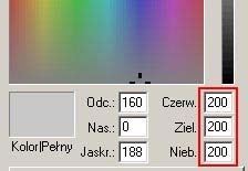
Now select color to paint. In Photoshop, to select a brush color you have to choose `Set foreground color' in upper color selection panel:
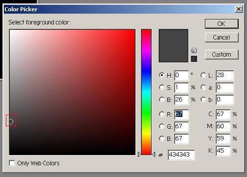
The color selection window will open. Now you have to remember that black indicates terrain ground zero and white indicates maximum height. The colors between black and white (tints of grayness) mean gradual terrain elevation. Clicking color selection opens `Color Picker' window:
37
Pay attention to small circle to the left (everything I describe I mark red on the pictures). To create an island select the color e.g. the same as on the picture. Then click OK.
And paint your island. I came up with something like that :
It does resemble an island, doesn't it?! Now look at the Brush Preset Picker button:
38
You can select the brush there, its size and thickness which will make exact and detailed painting easier.
Use your imagination and realize the idea of your map. My job is only to help you and explain how to do it. I think, now you should save your work. In Photoshop choose File->Save As. I suggest you to save your map in two formats:
- .psd standard Photoshop format Later on it will be easy to correct the map e.g. add
or remove something,
- .png standard Chrome game and ChromEd editor format.
First save your map as MyMap_H.psd and then MyMap_H.png.
The Save Image windows will open. To the left select the saving directory
(\Data\LevelsNet\MyMap\). Enter your map name (MyMap_H).
This way the first step of map creation is finished you made the height map that the
ChromEd editor will use for terrain generation. Later, you will modify the terrain by using the Terrain plug-in. More: in section about terrain modification.
39 3.3 Color map
Since you already have the terrain now you have to overlay the color map. This will be
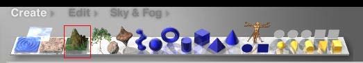
done by ChromEd editor. But before that you have to generate the color map first. As I mentioned before the color map is just a texture that later on will be overlaid on the height map. Now we use the Corel Bryce 5 program (it may be any other version of this program, I used this one). So start Bryce. Click `Create Terrain' on the tool bar:
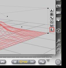
In this way Bryce created standard terrain grid. Next to the terrain grid, to the right, there is the Edit Object icon (`E' key). Click the icon:
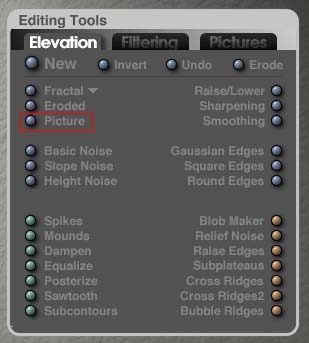
The new opened window enables to modify the terrain. Because you want to use the map that has been created before in Photoshop you won't create it in Bryce (you can also create the height map in Bryce but I won't describe it in this document). So, first load the height map. Use the Editing Tools on the right side. Click `Picture' on the Elevation tab:
40
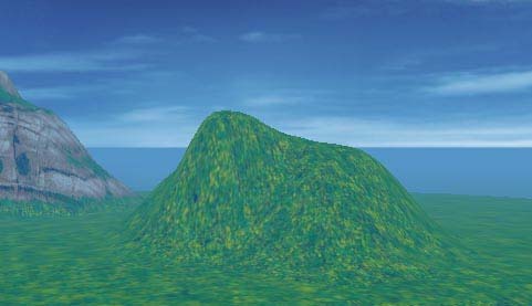
and open your height map MyMap_H.png. After the loading, on the upper right side you can see the terrain in `3D Preview' window. You may rotate this preview by holding the right mouse button and moving the mouse. My terrain looks, more less, like this:
Now you have to set the resolution of your height map. As you recollect, your height map is of 257x257 resolution so in Bryce you also have to set the same but without enlarging it by 1 pixel, that is 256x256. To change the resolution click the last, grate resembling icon and select `256 fine' option:
41
You have to provide that the height map is always the same. Because you created the height map of 257x257 resolution, in Bryce set the resolution to `256 fine'. If your height map was 513x513 you would have to set it in Bryce to `512 ultra fine' etc. Finally, confirm all performed operations by clicking the proper button:
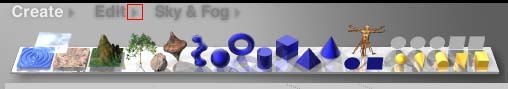
As you can see the terrain grid was modified by your height map. The terrain is ready, it's time to overlay the material (texture) that will imitate terrain sort of your map. The Bryce program has several material sorts build-in, starting with rocky terrains and ending with deserts or grassy terrains. To overlay this material you have to click `Material Preset'. It is a small triangle right to `Edit' menu, just above the tool bar (at the top of the screen):
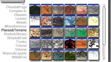
The `Materials' window opens. Now click `Planes & Terrains' and to the right select the proper material. I give you free hand here . I chose `Grassy Peaks III':
42
Confirm your selection by clicking the proper button:
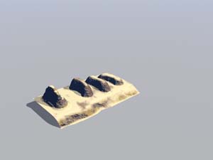
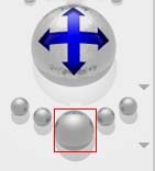
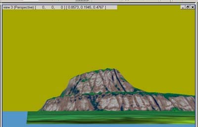
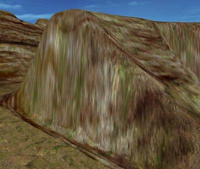
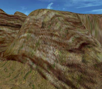
Now you can see how your terrain with overlaid color map looks like (more less). To do so, click `Render' (large sphere at the bottom left side of the screen):
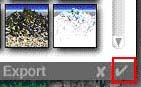
Rendering may take some time. Additionally, you can set the camera angle to better see the rendered terrain. This angle can be set by the large sphere with four blue arrows (you have to hold the left mouse button on this sphere and move the mouse). Now, export your terrain along with the bitmaps. Those bitmaps represent material overlaid on the terrain and they will be used for color map creation. At the top of the screen there is the hidden Bryce menu. When you move the cursor to the top of the screen this menu will appear. There, choose File -- >Export Object:
43
Enter the terrain name in proper field. For now, it may be any name, even default one. Select `3D Studio 3DS Files (*.3ds) (Mesh Export)' in `Save as type'. This is the 3D Studio (3D Studio MAX) file type. In this way the file will be generated that later on can be loaded into 3D Studio MAX program. Several bitmaps will be generated that will be transformed into the color map of your map.
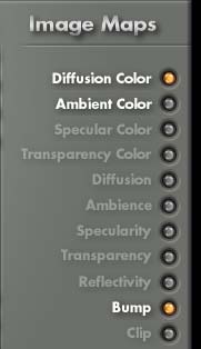
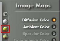
After clicking Save, the Export Terrain window opens. To make your color map more realistic and more detailed you have to alter some settings before exporting. Most of all, you only need just two bitmaps: `Diffusion Color' and `Bump'. To do so, on the right side of the screen (the Image Maps panel) uncheck unnecessary bitmaps (only `Diffusion Color' and `Bump' should be checked):
44
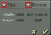
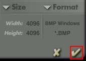
Increase the resolution of those bitmaps. You have to always remember to set the maximum resolution i.e. 4096x4096. This way the color map will be very exact and detailed. Later on you will decrease it to 2048x2048 to smoothen edges etc. Those bitmaps should be saved in .bmp format file which will avoid all distortions caused by bitmap compression (this would happen while using .jpg format file). The bitmap resolution and format file can be set by selecting appropriate options from `Size' and `Format' lists, just above the Image Maps panel:
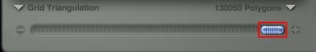
In the end increase the terrain grid circumstantiality. To do so, increase the polygon number of your terrain. Use the slide bar at the bottom of the screen:
Slide it all to the right end (just like on the picture above). Before you start bitmap export refresh terrain preview window by clicking the button:
45
Refreshing may take a while. To start exporting, click the appropriate button:
The export process will begin and its progress will be visible on the screen:
As any other program, Bryce as well is not a perfect program and has several bugs. It
may happen that during the export the progress window won't appear which doesn't mean that the process hasn't started! In such case the end of export process is signed by automatic closing the Export Terrain window and display of the program main window. And you may rest a while, have a tea , because export will take a while. The export time depends on e.g. CPU speed, RAM quantity. Additionally, each of the exported maps will take proximately 50MB on your disk. After the export I suggest to save your work in standard Bryce format file (choose File -> Save As). It will enable you to make any corrections later on.
And this is it. Bryce will not be useful for you any more, so you may close it (choose File -> Quit). Now start Photoshop. The Bryce program has generated two bitmaps: MyTerrain_diffcol.bmp and MyTerrain_bumpamt.bmp. Your file names may differ, depending on how you named your terrain during the export process, but for sure they contain _diffcol i _bumpamt, therefore I will use this names to the end of this section. Open both bitmaps with Photoshop. Choose File -> Open. Now overlay bitmap _bumpamt on _diffcol. To do so, click the title bar of _bumpamt bitmap to make it active. Click CTRL + A (select all) and then CTRL + C (copy). Next click the title bar of _diffcol bitmap (it turns active) and press CRTL + V (paste). Good, now the bitmaps are overlaid. One bitmap was created the color map! You have to set the proper blending (bitmap penetration). In Photoshop choose Layer -> Layer Style -> Blending Options):
46
The Layer Style window opens. Now from the Blend Mode list choose e.g. `Overlay'. You may choose any other blending e.g. `Soft Light', `Hard Light'. It all depends on what effect you want to get. I suggest some experiments:
You may also change the bitmaps penetration level using the Opacity slide bar (it is located just below the Blend Mode list), but if you leave it on 100% the color map will be more detailed.
Let's leave the value on 100.0. It will give much better effect. Ok, the bitmaps are overlaid. One bitmap was produced the color map . It may appear that after the blending altering the bitmap is too dark. Then you need to brighten it up. In Photoshop choose Image -> Adjustments -> Brightness/Contrast):
47
The Brightness/Contrast window opens. There, using the slide bars you may change the bitmap brightness (`Brightness') and contrast (`Contrast') as well:
You have to reduce the bitmap resolution to 2048x2048. In Photoshop choose Image -> Image Size. In the Image Size window type 2048 in `Width' and `Height' fields and then click OK.
At the end you have to flip the bitmap vertical (do not confuse with rotation!). In Photoshop choose Image -> Rotate Canvas -> Flip Canvas Vertical:
48
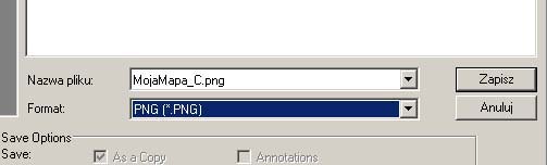
Done! The color map is ready. Easy, isn't it? Of course, you still have to save it. To do
so, in Photoshop choose File -> Save As and name your file. Let it be MyMap_C. Add _C to indicate that is the color map. Select the .png format file. Click Save. Answer `None' for the given question and click OK
For now the color map in this for is sufficient. Later on in section about the color map
modification I will describe how to add road etc. and use several filters which will give even more realistic look. I don't do this here because the map terrain will be still modified by Terrain plug-in, and the same the look of the map will be altered for sure. For now, let's be done with graphics programs and set to work with the ChromEd editor! You have the height map and the color map. You have everything that's necessary for work with the map so let's initialize the ChromEd editor, providing that you made acquainted with section about the ChromEd editor basics, because it will make work much easier.
3.4 Beginning your work with the ChromEd editor
During the ChromEd editor description I mentioned that the best way to work with the
ChromEd editor is work in one portview in perspective view. That is the camera view you may freely adjust. That's why the first thing that I always do is maximizing the perspective view (by default it is the lower right portview [view 3 perspective]). You may do this the same way as other Windows based programs:
49
Ok, but not to prolong the introduction let's get to work . Each Chrome game map
creation you begin with initializing the Environment plug-in (I mentioned about plug-ins while describing the ChromEd editor). It's one of the fundamental plug-ins without the map creation is not possible. Environment plug-in tasks: - class qualification of the given map (singleplayer or multiplayer), - terrain creation based on before prepared bitmaps (the height map and color map), - creation of object grid (otherwise the objects won't be able to be placed on the map), - sky and sun parameters definition, - fog parameters definition, - water parameters definition, - lightmap generation (described in section about lightmap).
Before you begin your work prepare the directory (I've already said that in chapter
one) you will store your map and everything that's related to that map (the height map and color map etc.). Create this directory in game directory, more exactly in multiplayer game subdirectory: \Data\LevelNet\. Now in this directory create the new subdirectory named e.g. MyMap. Copy your height map and color map do this directory.
Since you already know what the Environment plug-in is used for, let's use it and
create your first map. As I've mentioned before the ChromEd editor uses the term `level' not `map' but it is the same! Initialize the Environment plug-in by clicking its icon (the tool bar is described in detail in chapter about the ChromEd editor basics in section about interface):
The Object Attributes window opens.
NOTE: Maps created by the ChromEd editor are treated by the editor as objects. Keep this in mind! That's why after clicking the Environment plug-in icon the object attributes window opens, more on this topic in chapter about objects in section about object attributes.
First of all you have to state the map either the singleplayer or multiplayer one by
assigning the map to the proper class. By assumption this document is to teach you how to create the multiplayer maps but those of you who want to create the singleplayer maps won't suffer any harm . Click the dots button next to Class field:
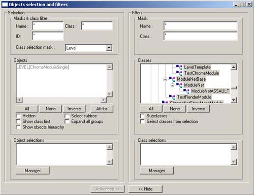
The Choose Class window opens. Now choose Module ->ChromeModule-> ModuleNetBase -> ModuleNet:
50
If your map is of the Assault mode (multiplayer game modes are described in chapter about the multiplayer game), then you have to assign to it the ModuleNetASSAULT class (Module - > ChromeModule -> ModuleNetBase -> ModuleNet -> ModuleNetASSAULT). Then click OK. For now leave your map as the singleplayer map. Why is that? Unless you do this you won't be able to test your map from the ChromEd editor's level. The singleplayer map needs to be of ChromeModuleSingle class. Therefore choose Module -> ChromeModule -> ChromeModuleSingle:
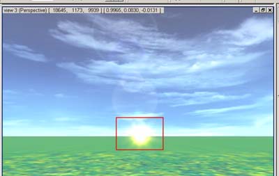
After choosing ChromeModuleSingle class click OK. There are several tabs left to the object attributes window. Each of them has a dedication. Now, you are in Java tab. In chapter about objects in section about object attributes I don't describe the Java tab that's why you can learn more about it right here. On this tab you set the attribute of the assigned class. It concerns all objects, the map as well (it is also an object, do not forget). All the available attributes are of assigned to object Java class. Here's the presentation of each ModuleNet, ModuleNetASSAULT and ChromeModuleSingle class attributes: - bDisableSun attribute in SUN section enables you to turn on/off the sun: `false' value turns the sun on, `true' value turns the sun off, - bDisableSunBlinding attribute in SUN section enables you to turn on/off sun blinding effect, `false' value turns sun blinding effect on, `true' turns sun blinding effect off,
- fDefaultClipFar attribute in VISRANGE section defines the player or camera distance till
which the faces will be rendered,
- fDefaultClipNear attribute in VISRANGE section defines the player or camera distance
from which the faces will be rendered,
51 - fMeshCullSize attribute in VISRANGE section defines the object size (in pixels) from
which the object will be rendered the smaller size the further objects are rendered,
- fVisRangeObjects attribute in VISRANGE section defines the player or camera distance till
which the objects will be rendered (those in distance more then fVisRangeObjects won't be visible, they will appear while player or camera closing to these objects),
- fVisRangeObjectsBlend attribute in VISRANGE section defines the player or camera
distance from which the objects start to be transparent (in fVisRangeObjectsBlend distance the objects are not transparent and in fVisRangeObjects distance are totally transparent),
- fTerrainError attribute in TERRAIN section defined the maximum allowable difference in
terrain simplification the bigger value the more terrain simplification, the lower value the less terrain simplification,
- sLevelName in NAME sections enables you to name your map (level), to change the map
name double click the proper attribute in value field,
Please remember that all the values in VISRANGE sections are given in units where
100 units = 1 m (this doesn't concern fMeshCullSize attribute where the value is given in pixels).
Generally, the VISRANGE section is responsible for the visual effects of the map
objects (e.g. to prevent far distant objects to `pop in' from nowhere but gradually, while player or camera closing) and also enables to `spare' the Chrome Engine far distant objects don't have to be rendered all the time.
And what is the terrain simplification? The more player or camera is located from the
terrain fragment the less details of this fragment are rendered (which are not visible from far distance anyways). When the player closes to such a terrain fragment those details are restored. This simplification can often be seen by naked eye the terrain seems to ripple etc. This is it for the VISRANGE section and the terrain simplification.
Some attributes (like bDisableSun) have already a preset the select value list. Because
you want the sun to be turned on set the bDisableSun attribute to `false' (default value). Of course, you may name your map, the same as I did (on the picture above).
Now it's seen what I mentioned while describing object attributes window (in chapter
about the ChromEd editor basics in section about object attributes). Namely, the Java tab (and Mission as well) has the feature that the attribute you didn't alter the value is gray highlighted and one you altered (even if you restored the default value) is black highlighted. This way you may easily seen what values are the default ones and what are altered. Additionally, in ModuleNet, ModuleNetASSAULT and ChromeModuleSingle classes there are attributes
52 enabling you to generate rain or snow on your map. More abiut this in chapter about event creation in section about rain and snow generation.
The next available tab in Environment plug-in, more exactly in object attributes
window, is Mission tab. Right now I won't describe it for it doesn't have any use while creating a multiplayer map. However, while crating a singleplayer map you may create initial events on such a map e.g. declare variables and initialize them, you may assign events to F2, F3, F7 and F8 keys. More on subject multiplayer maps in chapter about singleplayer game. Of course, other objects also may have the attributes in the Mission tab, it all depends on the class of the given object.
Let's get to another tab, Terrain tab. And now you're in the heart of the matter,
meaning that using this ChromEd editor tab you will generate the terrain. Let's begin! Click the dots button next to the `HeightMap' field. The standard Windows open dialog opens. Go to the \Data\LevelsNet\MyMap\ directory and select your height map (MyMap_H.png):
The next map is the color map. The same way clock the dots button next to the
`ColorMap' field and select your color map (MyMap_C.png). Following map is the detail map, described at the beginning of this chapter. To remind, it's a texture that will be overlaid the color map and be duplicated all over the terrain, which the player will see `under his feet' and around. Use one of the Chrome game standard textures. Naturally, you may overlay your own detail map but copy it to your directory (\Data\LevelsNet\MyMap\) to have everything in one place. If you do not have your own detail map, go to the \Data\Textures\ directory and choose a file e.g. CH_B_SpekaneBloto.png. It is the same texture I used in terrain generation description. Only the light map is left. Just now, you don't have it; you will generate it when your map is ready. So for now, use the standard light (preferable white) which will imitate the light map. Click the dots button next to the LightMap field and go to the \Data\Interface\ directory and choose ER_T_White.png file.
You still need to give your map size in `Map size' fields. The first field determinates the
terrain width (X), second height (Y) and third one length (Z). Remember, 100 units = 1m. I think that 250m x 250m size would be ok. The height map set to 40m. Enter the values: X=25000, Y=4000 and Z=25000:
53
NOTE: Your map size 250m x 250m (width and length) is not the whole map size
generated by the height map! To understand better this problem see the picture below:
The red marked area is your 250m x 250m! The places without reliefs (in black) will
contain the water, the same the ChromEd editor and the game itself doesn't consider it while setting the map width and length! I must admit that your map will be really small. The Chrome game maps are much larger. Maps you will create should also be large, particularly if you want to put buildings etc. there.
The `Detail tile' field defines the density of duplicated detail map. The given value
describes the duplication multiple factor in X and Z axes e.g. value `1' states that the DetailMap will overlay the terrain without duplication, value `2' states that it will overlay a quarter of the terrain (half of map in X and Z axes) etc. For now, leave the value `64'. You may alter the value later on if you find out that your detail map is too large (or too small). Besides, the proper value might be set with cut-and-try.
In the newest version of the ChromEd editor there is an additional Materials panel in
the Terrain tab:
You may apply the proper materials to your terrain and the horizon of your map. A
material is a special texture usually there are several textures, each of them has a specific and unique properties. If you want to apply the material to the map terrain click the dots button next to the Terrain field. To apply the material to the detail map click the dots button next to the `LOD field (LOD Level of Detail). To apply the material to the map horizon click the dots button next to the `horizon' field. Certainly, you may apply the materials to those three elements at once. Materials are located in \Data\Materials\Terrain\ directory. Unfortunately, this directory contains only the materials created by the Chrome game developers therefore they won't be much of use . Leave those fields empty, meaning not applying any materials.
54
Several options and tabs are left to describe but let me do that after the terrain
generation. I think you may do that now. To do so, click Apply, right to the Object Attributes window.
This way the terrain is being generated. It may take a while. The only element
indicating the process is the mouse cursor in hourglass shape. After the process is done it will return to the standard look. Ok, there's the standard cursor but no terrain . Easy, the terrain is there but it is not visible. Not enough that the observer camera is almost `in' the terrain but also it's turned backwards! But it's easy to change. Close the Object Attributes window. Press `G' key (observe mode, shortcuts and interface description in described in section about the ChromEd editor basics) and move your mouse to the left until you see your map (you have to move 180 degrees). Here is my terrain :
Press `G' key once again (exit the observe mode) and press ALT + P. Left click and
hold and move the mouse down to move the observer camera up. Still you are not above the terrain; you have to translate the camera. Press ALT + Z, left click and hold and move your mouse up until you are above the terrain (close to the two mountains). You may also rotate the observer camera. To do so, press ALT + R, left click and hold and move your mouse. It is a magnificent view, isn't it ?!
Now you need to create the grid that will enable to put objects on your map and move
on the terrain (without the grid it may be extremely difficult to operate the observer cameras in the portviews). You also have to add water and sky. All this you may do using the Environment plug-in so re-run it. Choose Terrain tab and find `Objects grid sizes' panel. You may define the area you will put objects on. I think that on your map you may put objects on everywhere the terrain is, so in `Maximum' fields enter X = 25000, Y = 4000 and Z = 25000 respectively.
There's an easier way too. Click `Get extends from terrain' button. Those values will
be automatically taken and filled on the map size basis (Map size):
55
This way the grid will be all over the map area. The `CellSizeX' field is responsible
for single grid cell width and `CellSizeZ' field for its length. I think that the grid cell 20m wide and 20m long should be sufficient so leave those values unchanged. To confirm the changes click Apply. The grid in not visible on the map!
Let's go through to the Sky tab. Here you may assign the sky look and set the sun
position. Let's begin with the sky. Click the dots button next to the Sky Mesh field and go to the \Data\Meshesh\Sky\ directory. There you have several ready-to-use objects representing the sky look. There's plenty to choose from indeed. I suggest NieboLevel01.3da. It is important that `Enable' button is pressed in, otherwise the sky will not be visible (turned off):
Since you've already chosen the sky you still need to confirm your operation. Again
click Apply. Bravo! You have the sky .
On the Sun Position panel set the sun position. Enter the sun position angle in XZ
plane (left right, `Angle in XZ' field) and YZ (up down, `Angle in YZ' field). For now I propose leaving the value `0' for both of the fields to see where the sun is. Confirm by clicking Apply and close the Object Attributes window. Press `G' and rotate your mouse.
You look around and.... There's no sun! This is one of the ChromEd editor bugs. The
sun will appear after the map re-loading. Since it is so, save your map first. Choose File - > Save As and go to \Data\LevelsNet\MyMap\ directory. Name your map e.g. MyMap and click Save. If your map is a singleplayer map then save it in \Data\Levels\MyMap\ directory. Your hard work has been saved and now you got the certainty that you won't have to do this all over again. Please always remember to name your map the same as the name of the directory you store it in (like in this example the map name is MyMap and the directory name is MyMap as well). Also please remember to not contain space in map name and to make them short (both map and directory names). I use max up to 15 characters. These remarks basically concern all names e.g. height maps, color maps etc.
56
Now re-load your map to restart your work. Choose File->New (to reset the ChromEd
editor) and then choose File->Open and select your map (MyMap). You can see the sun ! It is located at the bottom of the screen (adjust the camera):
Re-run Environment plug-in by clicking the `Lv' icon and go to the Sky tab. Type `15'
in `Angle in YZ' field and click Apply to confirm. As you can see the sun rises. If the Object Attributes window is in the way just close or replace it. Now type nay value in `Angle to the XZ' field e.g. `20'. As you van see the sun moved to the right. I think you van leave it just like that. I hope you comprehended the rule of setting the sun angle. The sun may be positioned in -180 +180 degrees range.
Now add the water round your island. In Environment plug-in select the `Water' tab.
Specify the water material there. To do so, click the dots button next to the Material field and go to the Data\Materials\Water\ directory. You may find several water materials there, each of them gives different effect but the most common used is water_texblend_refl.mat. Using this material will affect all other map objects (terrain, sky, etc.) to reflect in the water. You may experiment for your own and find out each material properties.
NOTE: Unless you set all the water parameters do not turn `Enable' option on yet. If
the parameters are bad the ChromEd editor might generate an error and you will have to re- run it, re-load the map and reset the water parameters which may be very weary. Also do not forget about saving your work often (use shortcut CTRL + S).
The Scale Tile field is responsible for duplicating the water material (very similar to
the detail map duplication). Basically, this value is left as default (0.001). By all means, you can make some experiments on your own and see what happens to the water while altering this parameter.
Now, let's have a closer look at the Extent panel:
57
Here you may define the water location and its height (depth). The first option `Whole
terrain' says that the water will be all around the terrain (which, by the way, is the option for you), more exactly where on your height map black color is, though is also depends on the water height level. If you made a pond in the middle of your map the water, obviously, would also be there. A thing worth noticing is that if your terrain has deep valleys and the water level is adequate high those valleys will be underwater, which may be not intended effect (e.g. you want to make deep trenches and the water level outside the terrain is high then those trenches will be submersed).
The second option `Part of terrain' is responsible for water to be only in designated
map location. NOTE: if you want the water to be all around your map and still you want to have a pond in the middle you have to check `Whole terrain' option! The `Part of terrain' option is used when there's no water around your terrain (e.g. the terrain lies in the valley surrounded by the mountains) and you want the water to be in the middle (e.g. in a river or a pond). In this case type the values of the water location (upper left and lower right point). To make your work easier the ChromEd editor designers added `Pick from terrain' button. Now click this button and then draw a rectangular area (as if you were multi-selecting objects) on your terrain you want to have the water. Those values are automatically taken from the area and you don't have to type them manually.
The next field is `Water level' field. It is the water height (depth). For the beginning,
enter value `300' and check `Enable' option (to turn water on) and then click Apply. You may see the water all around your area. Adjust the camera position to see the terrain rim. It's easy to notice the water is too low (unless you want it like this ):
58
So enter the other value. In my opinion, `930' (that is 9.3m) is quite right value. The
water is just at the very shore of the island. Now add the water waves. Use `Waves' and `Waves animations' panels:
The `Scale' panel (in `Waves' panel) is responsible for wave scale in X axis (width)
and Z (length). I propose entering the values: X = 10 and Z = 10. The `Amplitude' filed states the wave amplitude and `Speed' field the wave speed. I suggest entering `8' (Amplitude) and `4' (speed) respectively. The `FPS' field (in `Waves animation' field) defines the frame per second of wave animation. The default value is `10' and leave it like that. Click Apply.
Now your water is moving! Easy, isn't it! For safety reasons save your work. Choose File -> Save or just press CTRL+S. I also suggest making some experiments with water and wave properties, maybe you achieve much better effects.
I think it is high time to see the terrain form the Chrome game level . First of all you
need to add the Chrome game main character, which is Logan. To do so, use another plug-in Mesh Browser. This plug-in is described more in detail in chapter about objects in section about object adding. I just say how to add Logan without any unnecessary details. By default, this plug-in is already initialized and it is located on the right side of the ChromEd editor screen. If it is not there click the proper icon:
59
If this icon is already pressed (like on the picture above) it means that the Mesh
Browser plug-in is already active and should be located on the right side of the ChromEd editor screen. In this plug-in roll up the directory list to find \Data\Meshes\Logan\ directory:
On the list find Logan.3da file and select it, then click the Put Object button located at
the top of Mesh Browser plug-in. If it is not visible, use the scroll bar on the right:
Providing that the Put Object button is pressed click anywhere on your terrain (just
make sure it is a flat one). Do not place Logan in the mountains . Also make sure that Logan is on the ground, not in the air. To do so, click `Align to the ground' icon:
Now press `X' key. The same the observer camera will be centered on Logan. You
may rotate the camera around Logan. To do so, click orbiting icon (the ChromEd editor interface with all functions is described in chapter about the ChromEd editor basics in section about editor interface):
60
Left clicking and holding move your mouse to orbit around Logan. In addition, you
may zoom in and out by using the cursor keys or the mouse wheel (providing that mouse has a wheel).
Now you can see your map. I must admit that you succeeded with setting the
duplication multiple factor at the first time you don't have to alter the `Detail tile' field value in Terrain tab of Environment plug-in. As you can see, the texture under Logan feet is quite clear and it fits well. The same concerns the map height itself; the mountains are not too high. Let's leave it like that!
Press `S' key (object selecting mode) and double click Logan. A familiar object
attributes window opens. To impersonate Logan during the game you have to assign to it the proper class, the Single Player class. By default, Single Player class is already assigned to Logan but if, somehow, it is not click the dots button next to the Class field and choose MeshObject -> TriggerObject -> ChromeActor -> AnimActor -> Pawn -> PawnAnimated -> Player -> PlayerTriggered -> PlayerHUD -> PlayerSingle. Than click OK and next Apply. Close the object attributes window. Save the map (CTRL + S) and run the game mode by clicking the `Go' icon:
Click YES to answer the given question (Do you really want to run the game?) . After
a while you're in the game mode!
61 It is one of sensational ChromEd editor features you may run the game in editor
without running the whole game! For sure, it takes less time than initializing the whole game! Now play some on your map. In the end it is your very first map (however, it is not finished yet but most of work is already done). Press ALT + F4 keys (right ALT) to leave the game mode.
If you notice any fits and starts while moving in game mode then most probably the
water level is to high and you need to lover it a bit (`Water level' field in the Water tab of Environment plug-in).
Because your map is still a bit too large let's give Logan a mean of transportation. On
the object list of the Mesh Browser plug-in go to the \Data\Meshes\Vehicles\ directory and select the Jeep.3da object. Click the Put Object button and click anywhere on your terrain (to put the Jeep object on the map). Also make sure that the Jeep object is placed on the ground (click the `Align to the ground' icon. Press `S' key (object selecting mode) and double click the Jeep object. The Object Attributes window opens. You don't have to assign the class for the Jeep object is, by default, and object of Jeep class. Otherwise, choose MeshObject -> TriggerObject -> Actor -> ChromeActor -> Vehicle -> VehicleCar -> VehicleAttacker -> Jeep. Next go to the Mission tab and set `bActiveTrigger' attribute in TRIGGER section to `true' (select from the list):
This attribute triggers any event. In case of Jeep object possibility to enter and drive it
by the player. However, it concerns singleplayer maps only. For multiplayer maps the vehicle has to be assigned a different class. More about this in chapter about the multiplayer game. By the way, as you can see the Mission tab is very similar to the Java tab but there are other attributes available. Click Apply, close the Object Attributes window and save your map (CTRL + S).
And now Logan can drive the jeep ! As a rule, I would suggest this way of testing the
map that is adding Logan and a vehicle to transport. This will hasten and make easier the testing process. Sure, you may also replace Logan to any other place to have him there after the game mode initialization.
Only two tabs of Environment plug-in are left. First of them is the Fog tab which will
be described right here and second is Lighting (enabling light map generation for your map) which is described in section about lightmap. `Fog' is just a fog . It is used mainly for hiding far distance objects to not overcharge the Chrome Engine, to prevent the objects from `popping up' from nowhere while closing them. And finally the fog gives a better visual effect to your map!
Initialize the Environment plug-in and go to the Fog tab. There, select the fog color in
`Fog and background color' panel. You may do it manually by entering the proper values in `RGB' fields (Red, Green and Blue) or by clicking Pick Color button. The standard Windows color selection window opens where you can select the required color. In my opinion, the default light blue color (R = 85, G = 150, B = 200) is the best fog color. Select the fog type from the Fog type list:
62
To completely turn the fog off select NONE from the Fog Type list. If you choose the
LINEAR type of fog you also have to enter the proper values of the fog front (`Near' field) and the fog end (`Far' field). Those values are to be set in `Linear fog range' panel. If you choose the EXPOTENTIAL or EXPOTENTIAL2 type of fog then you also have to enter the fog density. You may set it in `Exponential fog density' panel. I propose selecting the EXPOTENTIAL fog type and density set to `0.0001'. To turn the fog on click the Enable Fog button and then click Apply to confirm the changes:
It's easy to notice that the fog appeared on your map. The map looks better at once.
To the left you can see the view without the fog, to the right with the fog. Make some
experiments with the fog settings. Choose LINEAR fog type and try to select the proper value of `Linear fog range' (I just say that the value in `Far' field has to be greater then the value in `Near' filed, otherwise the fog won't be rendered). But I think that for your map the EXPOTENTIAL fog type would be the best choice. The EXPOTENTIAL fog type floats all over the terrain and distant objects while the EXPOTETENTIAL2 fog type floats only over the distant objects. Basically, the EXPOTENTIAL fog type is suited for maps without any interiors.
In the newest version of ChromEd editor there is a new tab in Environment plug-in. at
the top of this tab there is info about the date and time of last save time (`Save time'),
63 computer (`Computer') and user name (`User') of the person who made the last change on the map.
The computer and user name concern the Windows system and the information is
based on who is currently logged in the system etc. Under this data there's a empty field. You can type a comment on your map:
Do not forget about confirming the changes by clicking Apply.
All right now. I think you know just enough about map creation for the Chrome game.
It is important you made some experiments on your own, just remember to save your work quite often. In this section it is all, you have your map, more exactly the map terrain.
3.5 Terrain modification
The terrain formation of your map is quite good bit, in my opinion it might be better .
So let's transform the terrain a bit. To do so, use the Terrain plug-in (this plug-in is not available in older version of the ChromEd editor). Initialize the Terrain plug-in (click `T' icon). The principle of use of this plug-in is quite simple. Using the brush you paint all over the map terrain. Depending on the brush settings you may rise or fall the terrain. You may smoothen the lines in the end (to get rid of unrealistic mountain edges etc.).
The plug-in window is located on the right side of the ChromEd editor screen. Let's
have a closer look. At the top, on the Terraforming panel, there are three buttons:
The Start button starts the plug-in. From now on you may pain with the brush over the
map terrain. To switch this function off click the button once again. The Undo buttons enables you to undo the last terraform operation with use of the brush. The undo operation of this plug-in is multilevel, meaning you may undo the terraformation to the very beginning of the terrain modification. In one word, if you don't like what you just modified you may undo this just by clicking this button. The Redo button restores the last undo of terrain modification. Obviously, since you may click the Undo button several times you may also click the Redo button several times. Well, it might happen that the modification you just undo was not so bad so you restore it by clicking the Redo button. In my opinion, in time of work with the Terrain plug-in you will get more familiar with Undo and Redo buttons.
You may define the current brush setting in the `Current brush' panel.
64
Here you may choose the brush shape. To do so, click the picture of the current brush
(red marked area on the picture above). All brushes are stored in \Data\Brushes\ directory, although, by default, there's only one brush . The brush shape you can make for your own because it's simply a bitmap. Such a bitmap has to be made in grayscale (the same as the height map) in 32x32 pixels size and in .png format file. Besides, have a closer look at the Round.png file provided along with the ChromEd editor:
The area in black is the area that doesn't have any influence on modifying terrain, the
area in white (and the tints of grayness) is the area with the influence on the modifying terrain. Clear? I hope so . Frankly, I never had to create another brush shape. The standard one is just enough. Use the slide bar to set the brush size.
You may also manually enter the brush size enter the required number in the field
above the slide bar. The default value is 3200 approx. 32m (100 units = 1m).
From the function list of the Tool panel you may choose the brush function:
and under the function list there are additional attributes which influence other brush functions (although not every function has its attributes). Here's the description of the following functions:
- `BlurFunction':
The brush will smoothen the terrain. Using this function you may get rid of all terrain distortions that cause your terrain to look unrealistically, meaning the vertexes are smoothen, the vertex height average is taken from close neighborhood vertex heights
65 (the neighborhood size is defined by `Neighborhood size' attribute), setting `Use only dest buffer' on `true' causes all the terrain modification to automatically update to the map terrain, setting it on `false' causes all the terrain modification to update to the terrain map at the end of the modification process, additionally, `BlurFunction' may be used for the color map smoothing,
- `PointHeightFunction'
The brush will shape the terrain, thanks to this function you may rise the terrain creating hills and lower creating valleys; the height you will rise or lower the terrain is controlled by the mouse move; the change of height is relative, meaning the base is current terrain height,
- `RelativeHeightFunction':
The brush will modify the terrain by the given value (in `Delta height' attribute); default value is 500, that is approx. 5m, 100 units = 1m, if you enter the positive number then the terrain is rised (hill creation) and if you enter the negative number then the terrain is lowered; the change of height is relative, meaning the base is current terrain height,
- `SetHeightFunction':
The brush will modify the terrain by the given value (in `Height' attribute); the default value is 500, that is approx. 5m, 100 units = 1m; additionally, using the `Mode' attribute you may restrict the vertex set you want to modify: - `Default' all the selected vertexes are set to the given height, - `Min' the vertexes lower then `Height' attribute are set to the given height; other
vertexes are ignored,
- `Max' similar to `Min' but only vertexes higher then `Height' attribute are set to
the given height.
The change of the terrain height is set in absolute value, equal to the `height' attribute.
66
Those are the basic brush functions. I should explain the definition of relative and absolute value. To understand this better let me remind you the look of your height map:
And so, the absolute value is calculated from the lowest point of the height map that is
all the area in black. The relative value is calculated from the point you start the terrain modification (where you click your mouse).
Back to the plug-in, after selecting the required brush function you may set few
additional parameters:
The `Power modifier' field defines the brush power (the value in 0.00 1.00 range), the
`Density' field defines the brush density (the value in 0 100 range) and the `Fade' field defines brush fade. To make your work easier the ChromEd editor developers enabled you to save your brush. To do so,click `Add to defined brushes' button:
The Set brush name window opens:
67 Enter the name of your brush in the Name field and click OK. The new defined brush appears on the list:
Now you may choose the brush from this list. The brush defining is useful mostly in
cases you often change brush parameters and settings. NOTE: If you want the defined brushes to be available during next ChromEd editor initialization then you have to click the Save Brushes button under the defined brush list. Unfortunately there's a bug in older version of the ChromEd editor: after the re-initialization the names of defined and saved brushes will be altered to default names (Brush000, Brush001 etc.). In the newest version this problem no longer exists.
Generally, there's no easy way to remove a single defined brush. There is, however, a
remedy . Just edit (using e.g. Notepad) `PredefinedBrushes.ini' file, find the brush name and delete the section starting with `brush()'. You may remove all brushes by deleting the `PredefinedBrushes.ini' file.
The terrain modified by the Terrain plug-in has to be saved in .height file. To do so,
click Save As:
The .height file has to be stored in the same directory as the map. Enter the file name
and save. I just add that the same function (saving to file) is realized by `Sv' icon located on the tool bar.
And what is the .height file? As you recollect the height maps created in Photoshop are
256 height levels maps (I mentioned about this at the beginning of this chapter). The .height files may be of 32 768 height levels and the same they are more accurate then the ordinary height maps. The disadvantage of this map is that they cannot be viewed (Photoshop doesn't display .height files). Click `Update terrain normals' button located under the `Save height file' panel:
to calculate normal all the map vertexes.
Ok, enough theory. Let's get to practice . Now diversify the terrain of your map. Add
few hills, create the beach and also a pond in the middle. Of course, it is your map and you know best how it should look like.
68
Let's begin with the beach. Select the area you want to create the beach and simply
lower the terrain. Decrease the brush size e.g. to `1500', choose `PointHeightFunction' and click Start. Move the cursor over the terrain you want to modify (but do not click yet). A `black spot' appears over the terrain to modify:
This black spot represents you brush and you already know how to resize it. Moving to
the brush center it gets more intense and the same the terrain modification will be more intense. Left click and hold the terrain you want to modify and gently move the mouse down. On and on, until you get the desired effect . Naturally, you may also rise the terrain, just move the mouse up. If you make any unwanted modification, just click Undo.
If you're done choose `BlurFunction'. Leave all the function attributes unchanged just
alter the brush power (`Power modifier' field) to `0.6' value (in other cases the terrain modifications will be too sharp) and smooth the lowered terrain. Set the brush over the terrain, left click and hold and move all over the terrain. This way, all the awkward places are smoothening. In this function you may also set the brush size and if the smoothening is too sharp then reduce its power by decreasing the `Power modifier' field value. You may also save your map choosing File->Save As or just pressing CRTL + S keys. While saving the map the .height file also is saved. It is automatically set as the height map of your map which you may check by initializing the Environment plug-in:
69
Do not be concerned that currently the color map does not fit the terrain map. Soon
you will make a new color map.
I also suggest you to smooth the edges of your map and mountains as well. Create a
small pond in the middle of the map. Choose `PointHeightFunction', set the brush size to e.g. `4000' and lower the terrain in the middle of the map (left click and hold and gently move the mouse down). Alter the brush size to approx. `1500' and lower the pond shore. If you want you may make the pond deeper. Finally, choose `BlurFunction' and smooth the terrain around the pond. This is the effect I got:
Now, add few hills. Choose `RelativeHeightFunction', resize the brush to `1500' and
set `Delta Height' value to `700'. Now click the area you want to rise the hill. As you may probably notice the terrain rises at once (you don't have to hold the left button and move the mouse). Click couple more times close to this area. Finally, choose `BlurFunction', resize the brush and smooth those hills. I came up with something like this:
70
Create two more hills like that and then save your map.
I mentioned before that you can use `BlurFunction' to smooth the color map. Since it
is not necessary to smooth the color map on your map let me use another example. See the picture below:
As you can see the hill slope doesn't look so well . Using the `BlurFunction' you may
smooth the color map on this slope which considerably affects the visual effect:
71
Much better, isn't it? Frankly, you didn't smooth the color map just the map terrain
where the color map doesn't perfectly fit the map terrain.
Thereon you finished the map modification. Perhaps those weren't great modifications
but I wanted to teach you the Terrain plug-in basics. Besides, it is your map and you may do it with it whatever you want .
Certainly, the .height file may be saved in the standard way by clicking the `Save as'
button on `Save height file' panel or by clicking the `Sv' icon. Just remember to store this file in map directory and to set is as the height map of your map (using the Environment plug in).
Great! Now modify the color map. A question comes to mind. For the color map
creation you need the height map but the graphics processing programs, like Bryce, cannot read .height format files. The ChromeE editor, however, can create the height map in .tga format file. To do so,click the color map generation icon:
The Get Terrain Height map window opens:
First, name the height map file and state the directory to store. To do so,click the dots
button next to the Path field and go to your map directory (\Data\LevelsNet\MyMap\). It is advised to save the height map in your map directory. Enter the file name MyMap_H (add _H to point out it is the height map). In your directory there is already a file with this name but it's in .png format file and this one is in .tga format file. Give the map width (`Width' field) and height (`Height' field). As I mentioned while describing the color map creation using Bryce the height map has to be of the same resolution! For sure you recollect that the height map is in 257x257 resolution so you have to stick to this resolution to the very end . Since this height map is only used for color map generation using Bryce it doesn't have to be 1 pixel larger vertical and horizontal. The same, it is enough to generate the height map in 256x256 resolution:
72
The `Omit terrain boundaries' option is responsible for the way the height map is calculated (it is calculated from the terrain boundaries). If the height map is to be used for the color map generation it is advised to check out this option. By checking the `Relative heights' option you will use 256 tints of grayness during the height map generation. Sometimes, it increases the accuracy of the generated height map. Click Ok and the height map is generated. You will use it in next section of this document.
So this is how the work with Terrain plug-in looks like. Basically, you could create the
height map using Photoshop and then shape the terrain using Terrain plug-in. But such a process would be quite labor-consuming and that's why I advise to always create the map outline using Photoshop.
3.6 Color map modification
Since the terrain shape of your map has been changed now you have to alter the color
map because it doesn't fit the map terrain anymore. In addition, I will show you how to make roads on your color map. But before you start you have to generate the bitmaps using Bryce once again. You already know how to do it; I described it in section about the color map, so if you forgot how to do it just take a look. I just prompt that this time you have to use the height map generated by the ChromEd editor, i.e. MyMap_H.tga file. Do not generate the bitmaps using the MyMap_H.png file for this map is already invalid !
After the new bitmaps are generated, open the maps with the Photoshop. For your
convenience I will use _bumpamt and _diffcol names. Basically, all the operations are the same as in section about the color map therefore I won't describe them in detail. Plenty of info about using Photoshop you may find in section about the height map and in section about the color map.
First of all you have to overlay the _bumpamt bitmap on _diffcol bitmap. You also
have to set the proper blending (I suggest `Overlay'). After the bitmaps are overlaid you may close the _bumpamt file, it won't be needed anymore. Now you have one bitmap the color map.
Let's add the roads on it but first you have to flip it vertical. To do so, choose Image -> Rotate Canvas -> Flip Canvas Vertical. After the map flipping add a new layer. Name it `Road' and pick the color of your road. I suggest color components: R = 127, G = 76, B = 57. If you don't know how to pick the color look in section about the height map.
Now select the proper brush and paint the roads on the color map. Choose the Brush
Tools from the Photoshop tool bar (at the bottom left side of the screen):
73
Now select the proper brush e.g. `Soft Round 65 pixels'. To do so,click the downward-
pointing triangle on the Brush Preset Picker button, which is located just below the main menu:
The list of available brushes opens and double click the `Soft Round 65 pixels':
You can select any other brush but I suggest the brush to be a `Soft' kind. And do not make it too big (you may set the brush size using the Master Diameter slide bar on brush list). Now simply paint (on the `Road' layer, the active layer is indicated by a small brush; to activate the layer click on its title bar) the road on the color map wherever you wish. Clearly, do not pain on mountains .
Ok. Before you continue, you have to combine all three layers into one. Choose Flatten Image -> Image:
This way you combine all three layers into one.
You're closing to the end . You have to apply few filters to your map and it's ready.
First, add a soft noise. Choose Filter -> Noise -> Add Noise:
74
The `Add Noise' window opens. First of all, check `Monochromatic' option and select `Gaussian' option in the Distribution panel. In addition, set the `Amount' field value to `12' using the slide bar (you may also enter the value `12' directly in `Amount' field). The noise has to be real soft!
Click OK. The second filter is `Spatter' filter. Choose Filter -> Brush Strokes -> Spatter:
In `Spatter' window set the `Spray Radius' field value to `10' and `Smoothness' field value to `5' using the slide bars (you may also enter the values directly in those fields):
Finally click OK. After applying those filters to your map it surely looks more
realistic, especially it is visible on the new added read.
Well, the color map is ready. Mine looks like this:
75
I've mentioned about this several times already but I'll do it once more. Always try to
make some experiments . Besides roads you may add other effects, a special hill color perhaps. See how many filters there are in Photoshop. Try few of them and maybe you come up with an outstanding effect! This document is only to teach you the basics of map creation.
Back to the color map. You have to change the resolution to 2048x2048. Choose Image->Image Size. In `Image Size' window enter the `2048' value in `Width' and `Height' fields and then click OK:
What's left is to save your color map. Choose File->Save as and go to the map
directory (\Data\LevelsNet\Mymap\). Select the .png format file end enter the color map name. You may save the color map as old map MyMap_C.png or any other. I suggest leaving the other file and saving the new color map as MyMap_C2.png:
In the PNG Options window leave `None' option checked and click OK. In addition, you may save the color map in .psd format file (Photoshop format file).
76
And that is really it! You have a new sensational color map. Initialize the ChromEd
editor, load your map, run the Environment plug-in, go to the Terrain tab, click the dots button next to the `ColorMap' field, go to your map directory (\Data\LevelsNet\MyMap\) and select the new color map (MyMap_C2.png). Finally, click Apply. And here's the result of your work:
Isn't it just great!? And it's gonna get even better when you add the vegetation to your
map but this is described in chapter about nature. From now on you will use the new color map (MyMap_C2.png).
3.7 Accessibility map
Now let's create the accessibility map. A little bit of theory before I start. Accessibility
map is another bitmap of .png format file. This bitmap has to be in 512x512 resolution and dichromatic white and red. On accessibility map the area in white is the area accessible for player to move, in red is the inaccessible area. The player can move everywhere but he cannot enter the deep water, a river, a lake or steep hill. To create the accessibility map use the ChromEd editor.
Always start with marking the terrain outline. It's the area inside which the player can
move but he cannot exit. Run your map in game mode (click `Go' icon) and move to the map edge. Be careful not to sink into water (this is one thing the accessibility map is used for to prevent the layer from sinking into water). If this happens and you cannot get out of water press ALT + F4 to exit the game mode. Then re-initialize the game mode. While at the map edge turn the Java parameters console on. To do so,press `~' key (tilde):
77
In this console type:
Player.UpdateAdditionalMap(1,512)
and press ENTER. Pay your attention to character case, do not use any spaces. The `Player.UpdateAdditionalMap() returned void' message should appear:
If you see any other message, make sure that you entered the `Player.UpdateAdditionalMap' command properly. You may close now the console by pressing `~' key.
Move (run) along the map edge trying to stay close to the water but not sink into it.
Naturally, if you spot any obstacle e.g. mountain, then pass it by. When you reach the starting point (eventually you will have to ) again turn the console on by pressing `~' and type:
Player.SaveAdditionalMap(tt.raw)
and press ENTER. Also pay your attention to the character size here. The `Player.SaveAdditionalMap() returned void' message should appear:
If you see any other message, check if you entered the `Player.SaveAdditionalMap' command properly. For now you may exit the game mode. To do so,press ALT + F4 keys.
In the main ChromEd editor and Chrome game directory (\Chrome\) a new file tt.raw
appeared that was created by `Player.SaveAdditionalMap(tt.raw)' command. The `tt.raw' is an example name, it is important the file has .raw extension. The file content was generated by `Player.AdditionalMap(1,512)' command. While walking on your map you draw the trace of your trip . See, the second parameter of this command is `512'. This is the resolution of accessibility map (512x512 pixels). Now, open the tt.raw file with the Photoshop.
The Raw Options window opens:
78
The `Width' and `Height' field values have to be `512'. Those values are
automatically taken from the tt.raw file. Now click OK. This is the content of tt.raw file:
It does resemble your map, doesn't it? There's a notch to the right because on my map there is a hill I had to pass by. Now convert this file to RGB format bitmap. Currently, only tints of grayness (Gray) are available, which is displayed on the title bar:
79
To convert tt.raw file to RGB format bitmap choose Image -> Mode -> RGB Color:
This way you got the RGB format bitmap, which is displayed on the title bar:
Ok. Now remember that accessibility map uses only two colors white and red. First, define those colors. Press `D' key and then `X' key. You just set white as the default tool color and black as the default background color. It is displayed on the color selection panel:
Click the black color. The Color Picker window opens. Enter the value `255' in `R'
field and value `0' in `G' and `B' fields:
Then click OK. Now in the color selection window you have the required colors i.e. white and red:
80
Great! On the bitmap white fill the inside of outlined area (the area accessible for player to move). To do so, choose Paint Bucket Tool:
Notice, that almost every icon of Photoshop tool bar has a downward-pointing arrow
at the bottom. If you left click and hold on the icon then the additional tools list opens. In case in the Pint Bucket Tool place there is the Gradient Tool, left click and hold it and you may choose the Pint Bucket Tool from the list.
After the tool selection, click inside the outlined area. It will be filled with white. If the
whole bitmap is filled with white it means there's an interruption in the outline. You have to find this interruption and fix it. First, undo the incorrect filling by pressing CTRL + ALT + Z key. Now choose the Pencil Tool:
From the Brush Preset Picker list on the upper Photoshop list choose `Hard Round 1 pixel':
Connect the interrupted outline and then re-fill with white the area inside. Press `X' (to
swap colors red becomes the default tool color and white default background color). Again choose the Paint Bucket Tools and fill with red the outside of outline area. You should come out with something like that:
81
For now it is enough. Save your work by choosing File->Save as:
In the Save As window enter the file name e.g. `tt' and select the .psd format file (standard Photoshop format file):
Let's get back to the ChromEd editor but do not close Photoshop yet. There are other places on your map that should be inaccessible for the player like high mountains or the pond. The player cannot go on the high mountains even without the accessibility map but it is better to mark such mountain on accessibility map. Run the game mode by clicking the `Go' icon. Move close to the mountain, turn the Java parameters console on (`~' key) and type the well known command:
Player.UpdateAdditionalMap(1,512)
82 Turn the console off and walk the mountain around. When you reach the starting point again turn the console on and type command:
Player.SaveAdditionalMap(tt.raw)
There's no need to change the file name. Exit the game mode (pressing ALT + F4
keys). Switch to Photoshop and load the new tt.raw file. Follow the instructions as before (in case there's a problem just see the beginning of this chapter). NOTE: This time you will fill the bitmap backwards, meaning you will fill with red the inside of the outlined area (the mountain inaccessible for the player) and with white the outside of the outlined area.
After you filled the bitmap in the proper way press CTRL + A (select all) and then
CTRL + C (copy) and switch to the previous bitmap (just click the bitmap title bar). Press CTRL + V (paste). This way you added a new layer to the previous bitmap. The new layer contains the second bitmap you just created. Make sure the new layer is the active bitmap (a small brush is next to the layer name):
Set the right blending now. To do so, choose Layer -> Layer Style -> Blending Options:
The Layer Style window opens. Now choose `Multiply' from the Blend Mode list and click OK. You should see something like that:
83
Now get back to the ChromEd editor and mark next area inaccessible for the player.
Mark all the areas like that. NOTE: You should create the accessibility map when there are no other objects on the map e.g. trees or buildings. The objects cannot be marked on the accessibility map, so what would happen if the object is building? The player simply couldn't enter it because the accessibility map made it inaccessible for him. That's why you should create the accessibility map right after the terrain creation. This is my bitmap which I convert to accessibility map:
84
Ok. Remember that the accessibility map has to be saved as the dichromatic (indexed)
map, so first convert it to the dichromatic map. To do so,choose Image -> Mode -> Indexed Color:
The question appears to confirm the layers combining:
Click OK. The layers combines in one and then the Indexed Color window opens:
85
Choose `Local (Perceptual)' from the Palette list. In `Colors' field enter the value `2' and uncheck the `Transparency' option:
Choose `Custom' from the Forced list (despite the option is selected reselect it!). The Force Color window opens. In this window you define two colors, i.e. white and red. To define the color click one of two available fields. The familiar Color Picker window opens. To define white enter the `255' value in `R', `G' and `B' fields and to define red enter the `255' value in `R' field and `0' in `G' and `B' fields. Naturally, you have to define colors separately. When you are done you should see two colors in the Forced Colors window:
86
Click OK. This way your bitmap is converted to indexed colors. Take a closer look. Using the Pencil Tool, remove single points from it. I marked them on the picture below:
Save your bitmap by choosing File->Save as. The accessibility map file has to be
stored in the map directory (\Data\LevelsNet\MyMap\) and has to have the same name as the map with the `_tt' ending. In my case it's MyMap_tt. The accessibility map file has to be saved in .png format file.
After entering the name and proper file type click Save in the Save As window. The
PNG Options window opens. Check `None' and click OK. That's it!!!
Get back to the ChromEd editor. Run your map in game mode by clicking the `Go'
icon. To load the accessibility map turn the graphics console on by pressing `\' key (backslash):
87
The graphics console gives you much information. It is divided in to pages. To turn pages use PAGE UP and PAGE DOWN key. But right now the graphic console is not important just type the command:
reload_tt_map
This way you load the accessibility map to your map. Basically the accessibility map is automatically loaded while the map loading but because you haven't loaded your map since the accessibility map creation you have to use reload_tt_map command. If you want to visualize the accessibility map in graphics console type the command:
vis_tt_map 10
where `10' value is the accessibility map visibility range. Turn the graphics console off by pressing `\' key. The white area around the player is just the accessibility map:
The area inaccessible to the player is marked in grey:
88
To turn off the accessibility map visualization, open the graphics console (`\' key) and type command:
vis_tt_map 0
The console is off. And you have the accessibility map. Always a step forward and your map gets more and more functional . If during the map testing you find a place you cannot reach and you should then use Photoshop to fix the accessibility map.
3.8 Lightmap
Only the lightmap is left for generate (what the lightmap is I already explained, for
recollection it is the light map containing e.g. the effect of object shadows on the ground). As I mentioned before the lightmap is generated at the very end of the map creation! Then your map contains all objects, vegetation etc. Naturally, you may generate is much earlier but you need to remember about updating it when you add any objects. In other case the lightmap generated shadows might be invalid. Assuming you had generated the lightmap and then removed an object there is the object shadow left on the map therefore you need to re-generate the lightmap.
Before you go on reading this document I propose a small overlap now read the in
chapter about nature. You will learn how to generate the vegetation on your map using the Forest plug-in. Thanks to that you will have grass and trees on your map and the same the visual effect of the lightmap will be better. After reading the chapter about nature (and adding the vegetation, of course) please continue reading this subchapter.
It is tie for the lightmap generation. To do so, run the Environment plug-in (by
clicking the `Lv' icon) and go the Lighting tab. First, enter the name of your lightmap. Click the dots button next to `File' field, go to the \Data\LevelsNet\MyMap\ directory and enter the name: MyMap_L (add _L extension to point out it is a lightmap). The ChromEd editor will automatically choose the format file (the lightmap is saved in .tga format file):
89
Now set the lightmap size (resolution). Generally, there is no size requirement (the
lightmap has to be squared and its size has to be a power of number 2) but I have few suggestions that might enhance the lightmap quality. First of all you need to remember that your color map is in 2048x2048 resolution (notice, that when generating the bitmaps using Bryce it was 4096x4096 resolution then you lowered it to 2048x2048). NOTE: since the generated lightmap will be overlaid the color map it is advised the lightmap resolution to be the same as the color map resolution. I suggest going even further to set the lightmap resolution to 4096x4096. By doing this the lightmap will be much more detailed. Naturally, later on you will have to change the size to 2048x2048 using Photoshop.
If you check `Use sun light' option then the sun light will be used as the main light
source during the lightmap generation. While lightmap generation for e.g. interiors without windows (buildings etc.) this light is needless and the lightmap generation process goes much faster (the use of sun light considerably slows the lightmap generation process down). The same applies the maps without sun e.g. night maps.
Your map is basically an open space and you have to use the sun light so check the
`Use sun light' option. The map has to be as much realistic as possible so trees, rocks or even high mountains have to put the shadow on the ground. Leave the `Raytrace in both directions' option checked (set by default). Checking this option causes the sun ray collision to be calculated in both directions. English speaking , it causes one-way face objects to put shadows as well (one-way face object is an object visible only from one side e.g. the grate wall is visible from outside). The examples of one-way face objects are grass and bushes which in the Chrome Engine are not 3D objects but simply always player directed textures (sprites). It is advised to leave this option always checked (although currently you don't have any one- way face objects) but this also slows the lightmap generation process down.
Leave the `Preview' option checked (set by default). This option is not serviced by the
ChromEd editor.
Now set the ambient light color. To do so, click color field in Ambient Color panel:
The standard Windows color selection window opens. You may select the standard
colors or create your own by entering the required RGB values. I propose entering the following values: R (Red) = 106, G (Green) = 106, B (Blue) = 106:
90
The ambient color is the color of object shadow. Basically, it is the darkest color that
may appear on the lightmap. All lightmap colors are in `Ambient color' and `Sun color' range (the sun color you will set in a moment). Click OK to close the color selection window. The Propagate Ambient window opens:
Leave the `Set in outside objects' option checked (set by default) and click the
Propagate button. This options cause applying the ambient color to every object. First option `Set in outside objects' applies the ambient color to every object without portal (you may find out more about portals in chapter about objects in section about portals i.e. all the outside objects (open spaced objects).
Second option (`set in inside objects') applies the ambient color to all group portal
objects (practically, all interior objects). It may be difficult to comprehend all this at the beginning (like in my case ) but in time, definitely, you will.
Ok, now set the sun light color. To do so, click the color field in Sun Color panel:
By default, the sun color is white (RGB=255). I suggest leaving this color.
Since you have already set the Sun Color, you may generate the lightmap now. To do
so, click the Generate button:
91
NOTE: The lightmap generation process may last really, really long, it all depends on
your computer power, the lightmap resolution, the map object quantity etc. I say it may even take several hours! So now you can take a brake , eat lunch, take a walk etc. You will have lots of spare time! The light map generation process progress is displayed at the bottom of the screen. Next to the Generation caption there is an indicator moving.
Ok now. Finally, the lightmap has been generated (50MB!!!). You have to adjust it to
your needs. Open your map with Photoshop choose File->Open and go to \Data\LevelsNet\MyMap\ directory and select MyMap_L.tga. If, by any means, you cannot see the file in `Open' window, change the format file to tga.
First of all, you have to light up the whole lightmap, the black level as well. If you
don't do this the shadows will look like pitch black, not shadow. To do so, choose Image -> Adjustments -> Levels:
First, light up the black level. Move the small arrow (I red marked it on the picture
below) to the right to set `80' value in the Output Levels field. Naturally, you may manually enter `80' value there. If the Preview option is checked then all the changes are visible on the lightmap at once:
92
After the value change (to `80') you can see at once that the black level on your
lightmap is changed and the shadows are not pitch black anymore. And that's what you wanted!
Now light up the lightmap. Use two arrows marked on the picture below:
The green marked arrow sets the lightmap brightness and the red marked one sets the
balance between dark and bright color. Move the green marked arrow to the left to set `220' value in `Input Levels' field (the field is also green marked, you may manually enter `220' value there). Then move the red marked arrow to the right to set `0.75' value in `Input Levels' field (the field is also red marked, you may manually enter `0.75' value there).
Ok. I think this are the optimal settings for your map lightmap. Of course, if you were
making a night map you would set other lightmap parameters. Practice, practice, practice . I assure you that the effects of your work will soon benefit.
Click OK to close the Levels window. Now, flip the lightmap vertical. Choose Image - > Rotate Canvas -> Flip Vertical:
93 The prepared lightmap has to be resized. As you probably recollect, your color map is
of 2048x2084 resolution and lightmap is 4096x4096. To resize the lightmap in Photoshop choose Image->Image Size:
The Image Size window opens. Enter `2048' value in `Width' and `Height' fields. If
the `Constrain Proportion' option is checked then entering `2048' value in one of the fields sets the same value in another field. After entering the proper values click OK:
94
Currently, my lightmap looks like this:
Save your lightmap. Choose File->Save As, go to the \Data\LevelsNet\MyMap\ directory and save your map as MyMap_L (.png format file). Click Save and in the PNG Options window choose `None', then click OK.
Now, load the color map. First copy the lightmap by pressing CRTL + A (select all)
then CTRL + C (copy). Select the color map and press CRTL + V (paste). This way you overlaid the lightmap on the color map.
95 Set the proper blending (bitmap penetration). In Photoshop choose Layer -> Layer Style -> Blending Options):
The Layer Style window opens. Now, choose `Multiply' from the Blend Mode list:
Finally, click OK.
If you notice that now the color map is too dark, you may light it up. Choose Image -> Adjustments -> Brightness/Contrast:
The Brightness/Contrast window opens. Use the Brightness slide bar to adjust
brightness (sliding left you light down and sliding right you light up). Use the Contrast slide bar to adjust contrast (sliding left to decrease contrast, sliding right you increase it). As you can see, I lighted up my light map (`Brightness' is set to `25')
96
Done! Save the modified color map as MyMap_CL (I add _CL extension to point out
that it is the color map combined with the lightmap). I suggest not overwriting the old color map, you may use it as a safety copy. Choose .png format file. Click Save and in the PNG Options window choose `None', then click OK.
Now, initialize the ChromEd editor, run Environment plug-in (by clicking `Lv' icon)
and go to the Terrain tab. Change two maps: in `ColorMap' field select `MyMap_CL.png' and in `LightMap' field select MyMap_L.png:
Click Apply to confirm the changes. Bravo! You got your map with the lightmap. Here is the result:
I just remind you that the lightmap should be generated when the map is 100% ready (it
contains all objects). Also remember to put the light map on the vegetation generated by Forest plug-in. To do so, run Forest plug-in and click `Update trees lightmap' on `Update' panel:
97
I think now you know how to generate the lightmap.
3.8 Minimap
In this chapter there's only one item left: the minimap. The minimap is just a map
(satellite photo) you open pressing `M' key (by default) during the game. Additionally, a part of this map is seen at the bottom left side of HUD. The satellite photo is done in the ChromeED editor.
First, click `Take satellite photo' icon located on the tool bar on the left side of the
ChromEd editor screen:
The Take Screenshot window opens. Name the satellite photo first. To do so, click the
dots button next to the File Name field. Go to \Data\LevelsNet\MyMap\ directory and enter the name: MyMap_S (add _S extension to point out this is the satellite photo file). Also enter the values in `Width' and `Height' fields. I think that the default 512x512 is quite enough
Naturally, the higher photo resolution the better quality but the Chrome game itself
will properly resize the photo to fit the minimap frames so there's no point to set the higher resolution. In addition you have to state if this is the picture of the whole terrain or just particular terrain part. You may define it in the Terrain extent panel.
First option `all' concerns the whole terrain. So if you want to take a satellite photo of
the whole terrain, check this option:
Second option `partial' concerns the part of the terrain. You may define the area you
want to take satellite photo of. You may enter the coordinates manually or click the Pick from
98 Terrain button and select the rectangular area (the principle of this button work is the same as the button determining the water location):
If you're all set, click OK. Now you have to flip (not rotate!) vertical and horizontal this photo. Open the MyMap_S.tga file with Photoshop (the satellite photo is saved in .tga format file). Choose Image -> Rotate Canvas -> Flip Canvas Vertical and then Image -> Rotate Canvas -> Flip Canvas Horizontal
And you have your satellite photo ready that you may use for the minimap. All you
have to do is to save it. Enter the name: MyMap_S and choose .png format file. Click Save and in the PNG Options window choose `None', then click OK.
Get back to the ChromEd editor. Initialize the Environment plug-in and go to the Java
tab. Click the dots button next to the `slnGameMap' attribute in MAP section. This buttons appears after selecting the `slnGameMap' attribute:
and select `MyMap_S.png' file. Click Apply to confirm and close the Environment plug-in. run the game mode (clicking `Go' icon) and while in game mode press `M' key:
99
That's all about the minimap. It is advised to make the minimap satellite photo at the
very end, right after the lightmap generation, when the whole map is ready. Then the minimap will be most accurate (terrain shape, map objects etc.).
Chapter 4 Nature 4.1 Introduction
In this chapter I will tell you how to add some nature to your map. By saying `nature' I
mean elements like vegetation (grass, trees, etc.) and all sorts of rocks (boulders etc.). To add some `nature' elements use the Forest plug-in. This plug-in is designed to generate many objects of the same kind in the given area. First of all, it may be used for grassland and forest generation but it also have the possibility to generate rocky fields or even groups of buildings! Because of the fact that in most cases this plug-in is used for grassland and forest generation I will use term `vegetation generation' in general.
You have to remember that the objects generated by the Forest plug-in are not treated
the same way as objects generated by Mesh Browser plug-in. The Forest plug-in generated object attributes are not available for you.
Also there's a difference between grass and a tree. Namely, a tree is an object
represented by a mesh (a .3da file) and grass is represented by a single texture (.png) file that always faces (the visible side) the player. You may find trees in \Data\Meshesh\Naturals\ directory e.g. DrzewoSwierk.3da and grass in \Data\Meshesh\Textures\ directory e.g. CH_T_Trawa2.png.
The principle of the Forest plug-in use is quite simple: to create layers. Each layer
contains separate kind of objects e.g. grass layer will contain the grass textures, the tree layer contains the tree objects etc.
The standard layer scheme (starting from the top):
- rock layer,
100 - tree layer, - other vegetation layer (e.g. bushes), - high grass layer, - low grass layer, - terrain layer.
The layers are generated successively starting with the lowest to the highest. From the
scheme above you can see that first generated layer is the low grass layer, then the high grass layer and so on. Finally, the rock layer is generated. Each layer generates its own objects.
When the objects are put on the map they remove those objects that block their
position (are too close). It considers not only the object size but also the closest distance to another object of the same type (in case of trees it considers the same mesh, in case of grass the same texture). In few words, the higher layer cuts out the objects from the lower layer (if needed). The last generated layers (the uppermost) have the most affect on the final look. Naturally, each layer parameters and the layer object parameters you may set using the Forest plug-in.
Ok, but how the Forest plug-in knows where to generate the vegetation? Well, for this
purpose you generate the density map. The density map is simply a dichromatic bitmap white color indicates the vegetation area (maximum density) and black color indicates the area without vegetation (lack of density). The in-between values (tints of grayness) are interpolated. Each layer may have its own density map but you can freely use one density map for several layers. To simplify the density map the layer object appears in area in white and does not appear in area in black.
But before you generate the vegetation on your map take a closer at the Forest plug-in.
First, I describe the upper part of the plug-in:
101 On the left side of the Layers panel there is a layer list containing the given layer objects. Notice, that the layers are generated from the lowest to the most upper one. Take a closer look at one of the layers:
It is easy to notice the layer name is `Grass' (next to the layer name there is the density
map name and the directory path to the density map file). Below the layer there are objects of the layer, in this case the grass textures (CH_T_Trawa4.png, CH_T_Trawa3.png etc.). The grass layers are indicated by `V' at front:
and the layers containing objects (meshes) are indicated by `X' at front:
If there's the layer name without any indicator then this layer will not be rendered (you may select and unselect the layers to render):
To distinguish the layers from the objects, each object is indicated by `|----`:
To the right of the Layers panel there is a group of buttons:
102
Pressing the Properties button you may set the selected layer or object properties. The Move Up button enables you to move the selected layer or object one position up on the list, and the Move Down button enables you to move the selected layer or object one position up on the list. As I mentioned before the layers are generated in the proper sequence so using this two buttons you may re-order the layer sequence. The object sequence does not matter. You cannot transfer objects between layers. The next button is the Add Layer button. By using it you may add a new layer with objects represented by meshes (e.g. trees). The new layer will appear above the selected layer on the list. Later on, you may alter the position by using the Move up and the Move Down buttons. By using the Add GLayer button you may add a new layer with objects represented by textures (e.g. grass). Also this new layer will appear above the selected layer on the list and later on, you may alter the position by using the Move up and the Move Down buttons. The Add Object button enables you to add an object to the selected layer (depending on the selected layer you may add an object represented either by mesh or by texture). The Delete button removes the selected layer or object. The Delete All button removes all layers and objects from the list.
Under the layer and object list there are three additional buttons:
Using the Export button you may export your layer and object list to .fd2 format file, using the Import button you may import a layer and object list from .fd2 format file. The Append button enables you to append the earlier exported list to the current layer and object list.
But why export and import layer and object list at all? You may simply create a layer
and object list template, export it to .fd2 format file and later use it for the map creation. It will help you not to repeat all aver the same operations for each single map.
Under the Layers panel there is another panel, the Generate Options panel with four
buttons on:
Clicking the Generate button you start the vegetation generation process based on the layer and object list. After clicking this button, the Generating Trees window opens:
Here, the vegetation generation process progress is displayed. Clicking the Start button starts the generation process. In the Current' Layers field the current layer name is displayed, the Layers progress bar indicates the total layer generation progress and the Objects progress bar displays the current layer generation progress. Press ESC to close this window.
103
NOTE: If you generated the vegetation and re-clicked the Generate button then the already generated vegetation would disappear from the map. The vegetation generation process may take a while, even up to several hours! It all depends on the map size, the layer quantity, the density map of each layer and each layer and object settings.
Another button is the Degenerate button. Clicking this button removes already generated vegetation. The Select All button causes all layers from the list to add to the generation process. As I mentioned before you may select the layers to generate (by checking the proper option in layer settings, more in next section). If you want to make sure all the layers from the list are generated just click this button. The Deselect All button removes all the layers from the vegetation generation process, the game nothing will be generated.
The next panel of Forest plug-in is the Global Parameters panel:
On this panel you may define the range and rendering way of generated trees (this does not apply to other objects represented by meshes e.g. rocks and objects represented by textures e.g. grass). In `View distance' you may set the visibility range of generated trees. The trees distant from the player (or the camera) are not rendered. The default value is '22 000' that is approx. 220m (100 units=1m). The higher visibility range the slower might map work (it depend on its size and quantity of generated trees). In `Skip LOD' field you may define how many levels of detail are omitted while trees rendering. The default value is `0' meaning all tree objects are normally rendered. Entering the positive value causes the successive levels of detail to be omitted (more info on this you may find in chapter about objects in section about object attributers, while describing the Misc tab of object attribute window). In `LOD selection factor' field you may set the tree level of detail selection factor. The default value is `0.3' if you want to render the trees more in detail enter the value `0.0001'. Do not enter the value `0'!!! The lower `LOD selection factor' value the slower might map work. In last field `Blend range' you may define the trees blending range (trees penetration). The distant trees from player or (camera) are not rendered (set the visibility range in `View distance' field). While player (or camera) closes them they start to appear. To avoid the trees `pop up from nowhere' effect the blending options are used the tree elements will successively appear. The default value is '15 000' that is approx. 150m (100 units=1m).
There are three buttons in the Update panel:
104
Pressing the `Update trees parameters' button you update all layer and object parameters changes. Pressing the `Update trees lightmap' button you put the earlier generated lightmap on the generated vegetation. As you recollect at the very end of map creation toy have to generate the terrain lightmap (see the chapter about the terrain creation in section about lightmap). So if you generated this lightmap you have to not only overlay it on the color map and assign to the map using the Environment plug-in but also you have to put it on the generated vegetation to display the lightmap shadows on trees and grass. The `Update terrain button' is used for terrain modifications (the height map) e.g. you added a valley but after the vegetation generation. Then the vegetation does not fit the terrain in area you created the valley but it is `in air'. Then click `Update to terrain' button.
Next is the Trees/grass Removing panel. There are three buttons there:
By using these buttons you may remove trees or grass from the selected area. If you generated vegetation and then decided that in this place you want to place a building, it's obvious that there should be no grass there. So you may remove grass from selected area. To remove trees, click the Remove Trees button and select an area. To remove grass, click the Remove Grass button and select an area. Using the Auto Remove Grass button you may remove the generated grass under given level. After clicking this button the Get Remove Grass Level window appears:
In the Level field enter the value under which all the generated grass will be removed and then click OK. By default, it is the water level (set using Environment plug-in), providing there's water on the map. If you generate the grass and some of this grass is located under the water then by clicking the Auto Remove Grass button you may remove the underwater grass.
On the last Tree Billboard Generation panel there is only one button located:
105
After clicking the Generate button, all trees will be transformed into so called billboards (a billboard is the object with the lowest LOD). The visual effect is for sure much worse but it will fasten the map work, particularly if the map is large and has lots of trees.
This is the theory of vegetation creation and Forest plug-in work. Now, let's get to
practice. At last you can add some greenness to your map . So, carry on!
4.2 Vegetation generation
Let's begin with the density map creation. As a matter of fact, let's create two maps
one for trees and another for grass. Initialize Photoshop. More in detail information about Photoshop work you may find in chapter about terrain creation in section about the height map and in section about the color map. Load your color map. I remind, the new color map i.e. MyMap_C2.png. Now create a new layer and name it `Grass'. Fill the new layer with black what means that in this areas there will be no vegetation at all. To set the black as default tool color press `D' key. Now fill in the new layer. To do so, choose the Pain Bucket Tool:
and click the new layer. Notice if this layer is active, the small brush indicates the active layer:
The newly added layer is already filled with black. Now, white mark the area to generate the grass. I suggest generating the grass all over the terrain besides roads and mountains. Well, you have to see the road and mountain location but the new black layer covers the color map. To fix this problem decrease the `Opacity' value of the `Grass' layer to e.g. `35'. To do so, in layers window click the small arrow and slide it left to `35' value (remember to set the `Grass' layer as active one):
Great! Now select white as the default toll color by pressing `D' key and then `X' key.
After this choose the Lasso Tool:
106
On the `Grass' layer simply select (draw) the areas you want to create grass:
After the area selection choose the Paint Bucket:
Next, simply click the selected area to fill it with white:
107
Again choose the Lasso Tools and select another area. Then choose the Paint Bucket Tool and fill the selected area in white. And so on... Repeat until all required areas are selected and filled with white. You may also magnify the color map using the Zoom Tool:
There is another way to select and fill the areas. Choose the Magic Wand Tools:
The use of this tool is a little bit different. After the tool selection you have to set the color map layer active. Now click (just click!) the area you want to fill with white. This tool automatically selects the homogenous area around the mouse cursor. Choose the Paint Bucket Tool, set the `Grass' layer active and click the selected area. The area is filled with white. Again choose the Magic Wand Tool, set the color map layer active and click the areas you want to fill with white. And so on.
This `select and fill' process in much faster but it can only be used with color maps
with homogenous areas, which is your case (at least mine) does not apply.
Since all the required areas are already filled you may save your density map. First
recover the `Grass' layer `Opacity' value to `100'. My density map looks like this:
108
Save your density map in the map directory (\Data\LevelsNet\MyMap\) as e.g.
Grass_F (I add the _F extention to point out it's the density map, by Forest plug-in name). The density map has to saved in .png format file:
Now create the trees density map but I leave it on your own. Using cut-and-try method
you may achieve an outstanding result. You may use the grass density map also as the trees density map.
After the generation of density maps it is time to work with the ChromEd editor.
Initialize the ChromEd editor and load your map. Run the Forest plug-in by clicking the
icon. First add the grass layer. Click the Add GLayer button
The Grass Type Layer Properties window opens:
109
In this very window all the layer parameters are set.
Let's begin . In `Name' field in the Main panel enter the layer name. Since it is the
grass layer simply enter `Grass'. Then click Browse next to the Bitmap field and go to your map directory (\Data\LevelsNet\MyMap\) and load the grass density map (Grass_F.png) you created before. In the Density field define the layer objects density. This is the value (in 0 - 100 range) representing the layer objects filling measure (grass in this case). E.g. if you enter `100' value then the layer is maximally filled with objects (grass). I suggest entering `20' value:
In the Extent panel set the map area you want to generate the layer objects. Because
you want the grass (it is the grass layer) to be all over the map terrain (according to the grass density map), just click Get From Terrain button:
This way the data considering map size are taken form the Environment plug-in (the Terrain tab). The fields in Extent panel are automatically replenished.
110
In the Size/Scale panel enter the single grass cluster size (in centimeters) and two
values defining maximum and minimum grass rescaling. I think that the `rescaling' term needs a bit of explanation. The rescaling is responsible for little altering the layer objects size. I suggest entering the `75' value in `Width' and `Height' fields (i.e. the single grass cluster is of 75x75cm size) and rescaling values `0.8' in `Min' field and `1.4' in `Max' field:
The rescaling is a random process according to `Min' and `Max' field values. Having the values given it is easier to understand the rescaling process.
Namely, the single grass cluster size is 75x75cm. While putting another grass object
on your map a rescaling value is randomly chosen form 0.8 1.4 range. Assuming that `1.2' value was chosen the single grass cluster size is rescaled by this value and the same the single cluster size is set to 90x90cm (75 * 1.2 = 90). Next `0.9' value is chosen. Now, the next single grass cluster size is rescaled by this value and the same its size is set to 67.5x67.5cm. Got it ? I guess so.
In the Move Parameters panel you may define the grass waving parameters. I would
suggest entering the following values: `Amplitude 1' = `3', `Amplitude 2' = `7', `Speed 1' = `113', `Speed 2' = `248' in both `Right vertex' and `Left vertex' fields:
In the Seed field of the Generate Options panel you may enter any value. This is so
called pseudorandom numbers generation seed. To provide the proportionate layer objects placement the initial drawing seed of the pseudorandom numbers generator is remembered. The thing is that each time you generate the vegetation the respective objects are put in the exact place. That's why I suggest not changing once entered Seed field value unless you have a good reason e.g. object penetration). You may start with `150' value. Also remember to set a different Seed field value for each layer.
In the Visibility range field define the percentage of the global visibility range of the
given layer. Simpler said, the bigger percent the higher visibility range in relation to the layer of the lower percentage. Naturally, it also depends in the layer objects size that's why I suggest applying a rule: the bigger layer objects are the lower percentage of the global visibility range. Since the grass is quite low (approx. 75cm) I propose entering `60' value. At the end check `Generate' option:
111
Checking this option adds this layer to generation process (if the option is unchecked then the layer doesn't take part in vegetation creation process).
Ok. All parameters are set. Click OK. The layer appears on the list:
Naturally, you may change the layer name. Simply select the layer and click the Properties button.
Now add the objects to the layer. In this case, objects are represented by textures. In
\Data\Textures\ directory there are plenty of grass textures to choose:
CH_T_Trawa.png CH_T_Trawa2.png CH_T_Trawa3.png CH_T_Trawa4.png CH_T_Trawa5.png CH_T_Trawa6.png CH_T_Trawa7.png CH_T_Trawa8.png CH_T_Trawa9.png CH_T_Trawa10.png
Browse these textures (e.g. using Photoshop). Well, the last three textures do not fit
your map for they are the winter grass textures. I suggest using CH_T_Trawa.png,
112 CH_T_Trawa2.png, CH_T_Trawa3.png and CH_T_Trawa4.png textures, of course the selection is, as always, on your own. Select the `Grass' layer on the list and click the Add Object button:
The Get Texture Name window opens:
Click the dots button next to the Name field on go to the texture directory
(\Data\Textures\). Load CH_T_Trawa.png texture. In the Density Field enter the object map occurrence factor (in 0 -100 range). For example, if you enter `80' value and for the next object you enter `50' value then the first type objects will be generated in greater number the objects of the second type. For now, enter `40' value.
In the Size field enter the object size factor. The thing is, not to let two different layer
objects to be generated close to one another. If you put the layer object on the place where another object of this layer is then the object too close is automatically removed form the map. It also considers the lower layers, meaning that if you put an upper layer object on the place where a lower layer object is (or is too close) then the lower layer object is automatically removed (as you probably remember from the introduction the upper layer cuts out the objects from the lower layer). For now enter `20' value.
The Distance field is responsible for the minimal distance between the layer objects of
the same kind. Also in here I suggest entering `20' value. Finally click OK.
This way you added the first object to your layer . Now, on your own, add next
objects, i.e. CH_T_Trawa2.png, CH_T_Trawa3.png and CH_T_Trawa4.png textures. I
113 suggest just altering the Density field value to `20' for CH_T_Trawa3.png and CH_T_Trawa4.png textures. As a result you should have something like that:
Ok, if you want you may try and generate what you just created . To do so, click
Generate button in the Generate Options panel:
Then click the Start button and the vegetation generation process starts. It will take a long time but I assure you: the result is worth waiting . After it's done the window opens with the information about the generated objects quantity:
Click OK now and here you are! The grass is on the map! Initialize the game mode.
Doesn't the map just look better, does it? I don't know if you noticed but in your pond there is also grass. For now leave it just like that, you may fix it later on.
Now add a new later the high grass layer. So, click the Add GLayer button and enter
the following values:
`Name'
HighGrass
`Bitmap'
Trawa_F.png (the same as for the `Grass' layer)
`Density'
5
`Width'
75
`Height'
150
`Min'
0.8
`Max'
1.2
`Amplitude 1'
3 (in both `Left vertex' and `Right vertex' fields)
`Amplitude 2'
7 (in both `Left vertex' and `Right vertex' fields)
`Speed 1'
113 (in both `Left vertex' and `Right vertex' fields')
`Speed 2'
248 (in both `Left vertex' and `Right vertex' fields)
`Seed'
65
`Visibility range'
25
Click the Get From Terrain button in the Extent panel and check the Generate option in the Generate Options panel. Then click OK.
114
And remember to place the new layer (`HighGrass') above the `Grass' layer:
If needed, you may move it up by using the Move Up button. As you noticed, next to
the new layer name there is `X' indicator meaning that this layer contains objects represented by meshes which is not true. It means that this layer cannot be generated because an error occurred. In this case this error is easy to identify simply the layer doesn't contain any objects yet.
Select the `HighGrass' layer and click the Add Object button. The familiar Get
Texture Name window opens. Enter the following values:
Add another object to this layer. The fields value are the same but this time load
CH_T_WysokaTrawaB.png texture. There are not high grass textures left .
If you want you may click the Generate button and check the vegetation on your map.
After clicking this button the previously generated vegetation will be removed.
Ok. Now let's add another layer, this time a tree layer. Sine a tree is an object
represented by mesh click the Add Layer button:
The Standard Layer Properties window opens:
In this window you may set the basic parameters of the layer containing objects
represented by meshes. In the Name field enter, as usual, the layer name. It is the tree layer so just enter `Trees'. Click the dots button next to the Bitmap field and go to the map directory
116 (\Data\LevelsNet\MyMap\) and load the trees density map. If you didn't prepare one just use the grass density map. In the Density field enter the layer density. This value represents, the same like for the layers containing objects represented by textures (grass), layer objects filling measure. I suggest entering `30' value:
In the Extent panel define the map area you want to generate the layer objects on. The
same, just click Get From Terrain button:
This way the data considering map size are taken form the Environment plug-in (the Terrain tab). The fields in the Extent panel are automatically replenished. Basically, you may define any other area then the whole map but it is much easier to select the vegetation area using the density map.
In the Seed field of the Generate Options panel you may enter any value. This is so
called pseudorandom numbers generation seed. I suggest entering `5' value. At the end check the Generate option:
Checking this option adds this layer to generation process (if the option is unchecked
then the layer doesn't take part in vegetation creation process).
Now click OK. On the list a new layer appears:
117 Remember, that the `Trees' layer has to be above the `HighGrass' layer so, in needed,
use the Move Up button.
Now add objects to the layer. Select the `Trees' layer on the list and click the Add
Object button. The Object properties window opens:
Click the dots button and to the \Data\Meshes\Naturals\ directory. There are plenty of
tree meshes to choose. Before you choose one you may see how it looks like. Simply insert the required object to your map (using the Mesh Browser plug-in). When you're done remove the object form the map. I suggest you to choose for your map DrzewoZwykle.3da object.
Ok now. In the Density field enter the object map occurrence factor (in 0 - 100 range),
enter e.g. `50' value.
In the Size field enter the object size factor. The same as during the generation of the
layer objects represented by textures (grass) the thing is, not to let two different layer objects to be generated close to one another. If you put the layer object on the place where another object of this layer is then the object too close is automatically removed form the map. It also considers the lower layers, meaning that if you put an upper layer object on the place where a lower layer object is (or is too close) then the lower layer object is automatically removed (as you probably remember from the introduction the upper layer cuts out the objects from the lower layer). For now enter `60' value.
The Distance field is responsible for the minimal distance between the layer objects of
the same kind. Since the tree objects are quite big I suggest entering `250' value.
In the Depth field define the object penetration of map terrain. Each object is put on
under the map terrain by the `Depth' field value. The purpose of this is to enhance the visual effect of the trees put on the steep surface (to hide tree roots). To be frank, I never had to enter other value then `0'. Even more, the trees won't be put on the steep surface. Well, maybe in your case they will but then using the cut-and-try method set the proper value (if you notice the tree roots are visible)
118
In the Scale panel enter the maximum and minimum rescaling values. Comparing to
the grass you don't set the single object size because the objects represented by meshes are of defined size. Although, the same in grass layers case, the rescaling is responsible for little altering the layer objects size. I suggest entering rescaling values '1.5' in `Min' field and `2.5' in `Max' field:
In the Value field of the LOD Selection Factor you may set the object level of detail
selection factor. If you want the trees to be rendered in detail then enter the value `0.0001. Do not enter the value `0'!!! The lower LOD Selection Factor value the slower might map work. In addition, if you want this factor to be considered then check `Enable' field:
I never had to use this factor so leave this field unchanged and make sure the `Enable' option is unchecked.
In the Visibility field define the percentage of the global visibility range of the given
layer. Simply said, the bigger percent the higher visibility range in relation to the layer of the lower percentage.
Checking the Collision Flag option causes turning on the collisions of generated
objects with other objects e.g. the player. The thing is to not enable players to walk through those objects (not like in case of objects represented by textures). Naturally, in case of trees you should check this option:
Finally, click OK. Let's add another object to the `Trees' layer. Make sure the layer is selected and click
the Add Object button. Enter the following values:
Make sure that the Enable option in the LOD Selection Factor panel is unchecked and
the Collision option is checked and click OK. The layer and object list should look like this:
Now diversify your map by adding few rocks (boulders). Add a new layer by clicking
the Add Layer button. Enter the following values in the Standard Layer Properties window:
`Name'
Rocks
`Bitmap'
Drzewa_F.png (the same trees density map or grass density map)
`Density'
20
`Seed'
75
Click the Get From Terrain button in the Extent panel and also make sure that the Generate option is checked. The `Rocks' layer has to be located above the `Trees' layer.
Add an object to the layer. To do so, select the layer and click the Add Object button.
Enter the following values in the Object Properties window:
Make sure that `Enable' option in the LOD Selection Factor panel is unchecked and `Collision' option is checked and click OK.
Add the last layer, the plants layer. Click the Add Layer button (the plants are objects
represented by meshes). Enter the following values in the Standard Layer Properties window:
120
`Name'
Plants
`Bitmap'
Drzewa_F.png
(the same trees density map or grass density map)
`Density'
15
`Seed'
58
Click the Get From Terrain button in the Extent panel and also make sure that `Generate' option is checked. The `Plants' layer has to be located above the `HighGrass' layer but below the `Trees' layer:
Use the Move Up and Move Down buttons if needed. Add an object to the layer. To do so, select the `Plans' layer and click the Add Object button. Enter the following values in the Object Properties window:
Make sure that `Enable' option in the LOD Selection Factor panel is unchecked and `Collision' option is checked and click OK.
Now it is really the end! You have all the layers, click the Generate button in the
Generate Options panel to finish the layer generation progress. Your map is already planted with vegetation . Now fix the error that occurred before. As you remember there is a pond on your map on which there is also the vegetation and you need to remove it.
Let's start with trees removal. Click the Remove Tree button in the Trees/grass
Removing panel:
121
Now simply select those trees (by clicking them) you want to remove. Generally, using this button you may remove other objects represented by meshes e.g. plants or rocks.
Click the Remove Grass button and select the area you want to remove the grass from
(left click and hold to select the rectangular area). Using this button you may remove objects represented by textures.
My map with vegetation (but without the lightmap) looks like this:
4.3 Final notes
Well, the only thing left is to generate the lightmap. How to do this you may read in
chapter about terrain generation in section about lightmap. After the lightmap generation and adding it to your map you have to overlay it on the generated vegetation. To do so, initialize the Forest plug-in and click the Update Trees Lightmap button in the Update panel:
This way on your vegetation the lightmap shadows appear. The same your map gets
more realistic look. You might wonder what field values setting are best. I just say I chose them using cut-and-try method. Basically, each separate map is unique and requires unique settings.
Yet, there are no objects like buildings etc. on your map. You will add them soon
enough. It doesn't matter which you add first to your map, buildings whether vegetation. Just remember to remove the trees and grass from the locations of buildings and water. With these words the vegetation generation process on your map is over.
122
Chapter 5 Objects
5.1 Introduction
In this chapter I try to describe the objects. I begin with each tool and window
description helpful while working with objects and end up with more advanced operations. In this chapter you get know everything about the Mesh Browser plug-in, the object attributes, object grouping and many more. This is the most complex chapter in this document! Let's begin.
5.2 Gizmo
One of the first tools you encounter while working with objects is a graceful named
tool the Gizmo . Basically, it's a virtual object representing another object's position and orientation. Using the Gizmo you may position and rotate the objects on your map. The Gizmo gets active while selecting any object (or objects). It look resembles the similar tool from other 3D graphics processing programs like 3D Studio MAX or Maya:
Left clicking and holding the blue arrow and moving the mouse you move the object
in Z axis. Left clicking and holding the red arrow and moving the mouse you move the object in X axis. Left clicking and holding the green arrow and moving the mouse you move the object in Y axis.
Left clicking and holding the blue-green triangle you move the object in YZ plane, left
clicking and holding the red-green triangle you move the object in XY plane and left clicking and holding the blue-red triangle you move the object in XZ plane.
Left clicking and holding the green circle at the the Gizmo base and moving your
mouse you rotate the object around Y axis. Using the red semicircle you rotate the object around X axis and using the blue semicircle you rotate the object around Z axis. NOTE: If you rotate in local axis coordination mode (`Local') then the Gizmo rotates it adequate direction alongside with the object. If you rotate in map terrain axis coordination
123 mode (`Word') then the arrows will always point the absolute X, Y and Z axes direction. You may choose the axis coordination mode from the list located on the tool bar:
Pressing SHIFT key while moving or rotating the object using the Gizmo and then
releasing SHIFT key and left mouse button you activate the object copy option. The Make Copy window opens:
In the Number field (in the Copy panel) enter the copy quantity you want to create. In the Selection Name field enter the selection group name (you can read about selection group creation in section about object selection). The created selection group you may quickly selected using object selection window. The Attach To Original Parent option enables you to attach the object copy to `parent' Finally, click OK.
This way the object copies are created. If you create a copy of the given object then
not all attributes of this object are copied. For example, when you copy the light object, then all the object attributes are copied as well, but when you copy the AI object (an object controlled by computer) then the assigned to this AI object patrol points (waypoints) are not copied.
Using `+' and `-' keys (not from numerical keyboard) you may resize the Gizmo. If
you selected one object then the Gizmo is located at the same place as the object, however when you select several objects then the Gizmo is located at the centre of this selection group, providing you're in map terrain axis coordination mode (`Word'). In case you're in local axis coordination mode (`Local') then each object of the selection group has its own the Gizmo.
The green circle at the Gizmo base (used for object rotation around Y axis) informs
you about the location of the object pivot point. An example to better understand this problem: Logan object's (Logan.3da) pivot point is located at its base (Logan feet):
124
however, the guard tower object's (WiezaMala_Kolumna.3da) pivot point is not located at its base:
So if you align this object to terrain the part of it will be dug in into the terrain because its pivot point is not located at its base. Please, pay attention to that!
5.3 Object attributes
In chapter about the terrain creation you already met the object attribute window. Then
those attributes applied to your map (the map is also an object!) and were connected with the Environment plug-in (also described in chapter about the terrain creation). Each object has its attributes you may modify using the object attributes window. The available attributes depend on the Java class assigned to the given object (it refers mainly to Java and Mission tabs.
Clicking the
icon you open the object attributes window (Object attributes).
Naturally, you need to select an object or objects before . The object attributes window can also be opened by double clicking the object you want to modify. The Object Attributes window:
125
The object attributes window contains several tabs. Each of them will be described but first let me describe the upper past of object attributes window.
The object name is displayed in the Name field. Naturally, you may alter it. It would
be best if the name was short and substantial and it is not advised to use spaces in object name (e.g. LargeTree instead of Large Tree). In the Mesh field the mesh file name is displayed (mesh is a .3da file representing the 3D object). Basically, the mesh is, by default, selected while putting on object on the map (using the Mesh Browser plug-in described in section about object adding) so there's no need to choose another mesh. Of course, if you want to then click the dots button next to the Mesh field. The Choose Mesh window opens in which you may choose the required mesh. You only have access to directories relating the ChromEd editor and the Chrome game. All meshes are in \Data\Meshes\. After selecting the require mesh from the mesh list click OK. The ChromEd editor will inform you that the mash has been changed and ask you to leave the default mesh name. The decision is yours . The mesh will be replaced with the one you chose but there's no need to do this that way.
126 Next you may assign the class (`Class') to your object. Click the dots button next to
the Class field. The Choose Class window opens:
The navigation in this window is Windows Explorer like. To unroll the directory tree branch click small `+' symbol, to roll click `-` symbol. To the left there is the list off all available classes, to the right the list of frequently used classes. The second list you may modify by adding and removing classes from the list. Just select the class and click `--->' button and the class is added to the frequently used classes list. To remove a class from this list, select it and click `<---` button. After the selection of the proper object class click OK.
Choosing the object class you have to consider the purpose of this object. The basics
of Java language you may find at the end of chapter about the Chrome game and more detailed information in chapter about the event creation, where you will use many classes and object attributes.
The Parent field displays the object `parent' name (providing the object is assigned to
any object hierarchy). To detach the object from the hierarchy click the `X' button next to the Parent field:
Another way to detach the object from the object hierarchy is clicking the proper icon on the ChromEd editor tool bar.
If the object belongs to any object group (you may read about it in section about object
grouping) then in the Parent field the object group name is displayed. In this case, clicking the `X' button removes the object from this object group.
127 There are four buttons at the bottom of the object attributes window:
The Load Defs button recovers the defined attributes settings of object's Java and
Mission tabs. How to define a setting? It's easy. It is defined automatically when you confirm the attributes setting by clicking Apply. From then on, this setting is defined. Every time you open the object attributes window and make some attributes modifications but you do not confirm them by clicking Apply, then by clicking the Load Defs button you may recover the last confirmed attributes settings.
The Dump Defs button (not available in older versions of the ChromEd editor) enables
you to save the current Object, Misc and Lighting tab attributes do .def format file. This file name is generated using the mesh name (not object name!) and is stored in mesh directory because this file is identified with the mesh (e.g. Jeep.3da).
If you change any attribute setting in Object, Misc and Lighting tabs, next confirm this
change by clicking Apply and finally click the Dump Defs button, then in main directory of the Chrome game a log file will be generated informing you if the .def format file creation is successful or now. You may view this log in any text editor e.g. Notepad. The exemplary name of such file:
DumpMeshDefs_d_m_rrrr_gg_mm.log
(d, m and rrrr stands for file generation date (day, month and year) and gg and mm defines the file generation time (hour and minute)).
Opening the log file you may read what was done:
Files saved without problems: data\meshes\vehicles\jeep.def
The first line informs you that file was successfully saved (`Files saved without problems') and the second line informs you about the file name and location.
If in log file you find something like that:
Errors in writing to files: data\meshes\vehicles\jeep.def
then the error in writing to file occurred. The most probable reason of this error is that the given name .def format file already exists but has read-only attribute set.
Anyways, why to bother with .def format files (do not confuse with log file)? Well, as
I mentioned before the .def format file is identified with the object mesh, so if e.g. you change the attributes setting in Object, Misc or Lighting tab of the object represented by Jeep.3da mesh and you save it to .def format file, then each time you put on this object on your map (this considers the current and future maps!) it will have the attributes setting that was saved while clicking the Dump Defs button.
And what would happen if you selected several objects of the same mesh (e.g. several
Jeeps)? In .def format file only the information about one object will be stored. In addition, you may read the following info in the log file:
128
Conflicts in files: data\meshes\vehicles\jeep.def
It means that the file conflict occurred (`Conflict in files'). Besides this, in .def format file all the attributes different for objects are properly marked.
The Refresh button function is very similar to the Load Defs button, but this button
affects all the tabs, i.e.: Object, Java, Mission, Misc and Lighting. Using the Refresh button, you recover the previously defined attributes setting on these tabs. As I mentioned before, the defined setting is the setting confirmed by clicking Apply.
The `Apply' button is used for object attributes modification confirmation. If you want
to apply the changes to the object, then click Apply. Otherwise, they are not saved!
Now, let me describe all the object attributes window tabs. Naturally, the tab
availability depends on the class assigned to the object so it may happen that one object may not have all described tabs.
The first tab is the Objects tab. In here, you may set all the basic information about the
object, i.e. its behavior (e.g. physics), collision type and many more (e.g. flags). Basically, this tab is not needed while map creating, but I try to get you more familiar with it, though I must admit it's rather technical stuff hard to understand.
The `Physics' panel is responsible for the object physics:
From the Type list choose the object physics type (its calculation mode, it is different for separate objects). There are 6 types to choose:
- NONE no physics (e.g. for buildings), - WALK physics for walking objects (e.g. the player), - 4WHEEL physics for four wheeled objects (e.g. the jeep), - FLY physics for flying objects, - FALL falling with gravity, - GRAVITYWALK walking with gravity.
In `Gravity' field you may define the object gravity value. It is interpreted in relation to physics type. In general, the lower value is the faster object falls (if the value is `0' then the object doesn't fall). The gravity interpretation:
- falling velocity - WALK type physics, - acceleration - GRAVITYWALK, FALL type physics, - mass 4WHEEL physics, - not considered FLY and NONE type physics.
The next panel is the Flags panel:
129
The Flags panel options:
- `Collisions' specifies if the collisions for this object are calculated, - `Block move' specifies if the collisions are calculated while object move, - `Block trace' specifies if the collisions are calculated while object tracing, - `FX particle collisions' specifies if FX's (special effects e.g. bullet marks) apply to
the given object,
- `Align to ground by normal' defines if the object is align to the ground according to
the terrain shape in this place, if this option is unchecked then the object is always vertical according to 0, 1, 0 vector (a bit above the ground),
- `Render as billboard (all such meshes)' defined for meshes, which is an exemption
all other flags are defined for single objects, it specifies the objects of the given mesh will always face the player or camera (like in grass case),
- `Static' defines the object as static (it doesn't move), - `Visible for Pathfinder' specifies if the object is considered while creating the AI
collision map (more about the object collision in chapter about singleplayer game in section about AI collision map),
- `Cull by size' object culling according to object size, not only the object distance, - `No animation' specifies if the given object may be animated, - `No animation refresh' specifies if the given object may be animated, without the
refresh for each separate bone,
- `Stop by Pathfinder' specifies if the object is considered as an obstacle by the AI
collision map.
And what the collision is? It's simple. If one object contacts another e.g. the player goes against the tree, then the object collision happens. When the objects collision happens, depending on the objects attributes setting' the Chrome Engine reacts for this collision e.g. it wont enable the player to walk through the tree. All objects controlled by computer (AI) need to have an objects collision map generated to let the computer `know' where the obstacles are and how to avoid them. More about the object collision in chapter about singleplayer game in section about AI collision map. Generally, while creating the multiplayer maps you don't have to change the object collision options. You may leave the default setting. Of course, there's no need to generate the AI collision map either .
The last panel of the Objects tab to describe is the Collision panel. It is responsible for
object collision setting:
130
The Type list defines the object collision type. The following options are available:
- ELLIPSOID the ellipsoid collision type the object is roughly described as Y axis
ellipsoid leveled to terrain Y axis, other moving objects treat this object as ellipsoid (used e.g. for characters, barrels and other symmetric objects)
- PERFACE per face collision type other moving objects analyze the collision with
every object face ( used for asymmetric objects e.g. buildings, trees),
- PERFACEOBJECT object per face collision type similar to per face type, but with
object detection, the same during the handlers calling the both object colliding are transferred.
The Action list is responsible for the action during the objects collision. The following options are available:
- STOP object stops and doesn't continue its move, - SLIDE object slides of the collided object, - BOUNCE object bounces of the collided object (according to normal physics in
collision point),
- GRAVITYSTEP option is not used.
The Handler Type list is responsible for the type of called Java handler. It defines if and with what parameters the Java handler is called. The following options are available:
- NONE no handler call, - CALL handler call with no parameters, - OBJECT handler call with collided object, - FULLINFO handler call with collided object, the collision point, the normal vector
in collision point and the vector defining the object translation to collision point.
The Trace Coll list defines the collision type in the moment of tracing release. The following options are available:
- COARSE_BOX collision with `big box' describing the character, - COARSE_ELLIPSOID collision with the ellipsoid describing the character, - ELEMENT_BOX collision with single `box' (describing a body part), - ELEMENT_ELLIPSOID collision with a body part described in ellipsoid, - PERFACE exact collision with the given face (`box' element), - EXTENTS the value set only for vertical collisions.
If you do not understand anything from above do not worry, I don't myself . And seriously, you won't use this tab and in case it is needed I will describe the option more in detail.
The next object attributes window tabs are Java and Mission tabs. However, I won't
describe them right here because they are strictly related to the class assigned to the object (which I mentioned at the beginning of this section) and the same the object destination.
131 As for the changing the attributes value it is quite simple. Some attributes have lists of
values you may choose the required value from. To manually enter the value double click the Value field and enter the value.
Other attributes need to have the objects assigned. To assign the object to the attribute,
first select the attribute then right click the object. From the context menu choose Set <...> as <...>.
To other attributes you need to add elements. To add a new element to the attribute
select the attribute and press INSERT key. To remove the attribute element select the element and press DELETE.
More details on these tabs you may find in further part of this chapter and also in
chapter about event creation, in chapter about singleplayer game and in chapter about multiplayer game, where you will learn to use classes and object attributes. I also mentioned those tabs in chapter about terrain creation in section about the Environment plug-in.
I just add that both of these tabs have an important feature. The attribute you didn't
change is highlighted in gray and the one you changed (even if later on you changed it to default) is highlighted in black. This way it is easy to notice the attributes that ha been changed.
Next is the Matrix tab (no, not the movie ). Using this tab you may precisely (even
0.000001 point!!!) position the object on your map and also rotate and scale it. The Matrix tab:
As you can see you may distinguish three sections on this tab. First of them is used for object positioning (`Position'), second for object rotating (`Rotation') and third for object scaling (`Scale'). Each object you may position, rotate and scale in X, Y and Z axes. Next, in `Spinners step' panel you may define the object positioning, rotating and scaling step.
The Whole Matrix panel enables you to copy, paste and reset all object values in the
Matrix tab. This way you may quickly remove one object values to another and you don't have to do it manually. The Reset button restores the default values for each section.
But what if you want to copy just the object position values? Well, the ChromEd
editor designers also thought about this . There are three small buttons at the top of each section:
132 The first one, `C' (`Copy') enables you to copy the values of X, Y and Z axes. The second one, `P' (`Paste') enables you to paste the copied values (respectively in X, Y and Z axes). The third one, `R' (`Reset'), restores the default values of section fields (usually it is `0.000000' for position and rotate fields and `1.000000' for scale field).
Under the `Spinners steps' field there is another field `Primary scale':
Using this field you may set the object scaling multiplying factor. E.g. if the scale of your object in three axes is `2.000000' and the multiplying factor (`Primary scale') is set to `5':
then after applying the changes (by clicking Apply) the object is rescaled to '10.000000' value in all three axes:
I must say, that while describing this problem I used the Logan object and after the rescaling he was of a magnificent size .
Well, you know the Matrix tab theory, let's get to practice now. Let's assume you
want to rotate the object 45 degrees in Y axis. You can do it in several ways.
First of them is simply entering '45 value in `Y:' field in rotation section:
and clicking Apply to confirm the change.
The second way is setting rotation `Spinner steps' value to `45' and clicking the small
upward-pointing arrow next to `Y:' field value:
133
Each clicking the upward or downward-pointing arrow increases or decreasing the field value by the value given in `Spinners steps' fields. NOTE: using those arrows for positioning, rotating or scaling then those modifications automatically apply to the object but manually entering the values you need to confirm the changes by clicking `Apply' button located at the bottom left of object attributes window (these buttons are described at the beginning of this section).
So this is the use of the Matrix tab. I just add that you may rotate the object in =180 -
180 degrees range (i.e. 360 degrees). Naturally, you may rotate the object using the Gizmo but it will not be precisely 45 degrees rotation (unless you're an eagle eyed ). If you use this tab quite often I assure you soon enough you get quite familiar with it. Also pay attention to the axis coordination mode. If you want to position, rotate, etc. objects according to the map terrain then this mode has to be set to `Word'.
The Misc tab. All the information concerning LOD (level of detail) is displayed here.
And what LOD is? Well, the Chrome game developers wanted their engine (the Chrome Engine) to be very efficient so they came up with an idea that the objects closer to the player or camera have more details then the far objects. While closing the player or camera they have more and more details. Of course, the process is very fluent and you shouldn't even notice a thing. This is how the Chrome Engine is very efficient even on a slower system.
Each object in the Chrome game can have maximum of 3 LODs. The Misc tab informs
you about the object LOD:
Basically, during the map creation this information is not essential, but since you may alter those values I will describe them anyway.
In the Total LOD Meshes field the object mesh quantity is displayed (it is easy to
notice that the object consists of three meshes, each of them of a different LOD).
In the Mesh Size field the information about the object mesh size is displayed. Next, the distance is displayed (the LOD Distances field for each of the three LODs
('1st', `2nd', `3rd' fields). You may see at what distance from the player or camera the object has to be to render the mesh with the proper LOD. Simply enter the LOD selection factor
134 value in `LOD sel. coefficient' field and click the Recalc button. This way you change the distance of LOD rendering.
Of course, not every object consists of three meshes. All buildings are one mesh
objects and they do not have LODs.
This tab is rather informative tab. During my work with the ChromEd editor I just
used it once or twice.
Next is the Anims tab. This tab is used to animate objects. It doesn't have any
influence on map creation. But it may be handy in the future while creating Java language code for mesh animation (it considers mainly the Chrome game modifications, which I don't describe in this document). Using the Anims tab you cannot create new animation frames but you may define the animation frames sequence. You may also view the given object mesh structure and also assign the proper animation sequence to the mesh (.scr format file). The Anims tab:
In the upper part the object mesh structure is displayed; in the lower one, the mesh animation list. Under the mesh animation list there are buttons enabling e.g. to play the animation, stop the animation, add new animation sequence etc. However, as I mentioned before, this tab doesn't have any influence on map creation progress therefore I won't describe it.
Next is the Info tab which also doesn't influence the map creation process. It displays
the information about the mesh materials and textures of the given object:
135
On this list you may see the mesh material with assigned texture (also the texture directory). Checking `Sort By Textures' option at the bottom of the list, the texture name will be displayed first (with the directory) and under it the material using this texture.
The Skins tab (not available in older version of the ChromEd editor). This tab enables
you to choose the object skin. I treat the skin like some kind of object clothes . In the Skins panel the list of available skins for the object is displayed:
To choose the required skin, simply click its name.
Below the Skins panel, to the left, the material list of default skin (DefaultSkin.3da) is
displayed. And to the right the material list of the current skin (Skins) is displayed. NOTE: the ChromEd editor doesn't refresh the list after choosing a skin. To refresh the list you have to close the object attribute window and then re-open it (you may also click the Refresh button but then you also restore the defined attribute setting, which may not be what you want). Choosing a new object skin doesn't have to be confirmed by clicking Apply button, the change is automatic after the selecting skin from the list. Here is couple of Logan object (Logan.3da) skins:
136
The last and one of most important is Lighting tab. Using this tab you may generate
the lightmap for objects (not terrain!). NOTE: Each map object needs to have the lightmap generated! You may do it for each object separately or for all objects at once. It is advised to generate the lightmap at the very end of map creation process. Also, it is a good habit to set the basic object lightmap parameters (e.g. the shadow color) just after putting the object on the map.
The generated terrain needs to be overlaid on the color map, but with the object
lightmap you don't have to do anything. It is automatically used just after the generation. First, let me describe the Lightmap Parameters panel:
First of all, to generate the lightmap for an object you need to check `Use lightmaps'
option.
`Sample per pixel' field defines the samples quantity calculated for each pixel of the
generated lightmap (the given value is squared, i.e. for '1' only one sample is calculated, for `2' four samples and so on; then the average is taken). Thanks to that the lightmap edge is smoother. `Texels' field is responsible for the lightmap exactness, meaning how many texels (lightmap pixels) per meter occurs. In both cases I suggest leaving the default values (`1' for `Samples per pixel' field and `1.00' for `Texels' field).
Next you need to set the ambient color. The ambient color is the color of the light (so
you may say `ambient light') that will be put upon the object. After clicking color field the standard Windows color selection window opens. You may select the standard colors or create your own by entering the required RGB values.
This is the object (in this case a jeep) with red ambient light:
137
The default ambient color is grey (RGB values: R = 106, G = 106, B = 106). The object with default ambient color:
Of course, it all depends on the wanted effects on your map.
Next set the flags (in the Flags panel):
Checking the first option: `Cast shadows' causes the object to shade.
NOTE: you need to check this option for all static objects, i.e. the objects that do not move on your map!
Checking the second option: `Receive shadows' enables the object to be shaded by
other objects (providing that the distance between them is close enough to shade one another).
`Lights' panel:
Checking the `Use all editor lights' option causes using all map lights (e.g. street
lamps light) during the object lightmap generation process.
Checking the second option: `Use sun light' causes using the sun light during the
object lightmap generation process.
138
The option selection depends on the object location. If e.g. the object is located
indoors then it shouldn't have the `Use sun light' option checked.
There is another option in the Generate Lightmaps panel - `raytrace in both directions':
Checking this option causes the sun ray collision to be calculated in both directions.
The thing is to make one face objects shade as well. One way face like objects are grass and bushes which in the Chrome Engine are not 3D objects but always player directed bitmaps. It is advised to leave this option checked, although it makes the object generation process longer.
Ok, all the parameters are set so let's start the object lightmap generation. To do
so,click one of the buttons in the Generate Lightmaps panel:
The first button `Generate' generates the lightmap for the current objects. The Generate For Objects button generates the object lightmap for all map objects. This process may take a while it depends on the options set and your computer power.
After clicking any of these buttons the Generation Lightmaps window opens (clicking
the Generate For All Objects button, you need to confirm the generation process for all objects):
If needed, press ESC to exit. Clicking the Start button starts the object lightmap generation process. The process is displayed in this window:
- the `Current object' progress bar informs you about the current object lightmap
generation progress,
- the `All objects' progress bar informs you about the total lightmap generation
progress.
After this is done in your map directory a new subdirectory is created (\LMaps\) containing .lmap format files for each map object. Those are the object lightmaps. NOTE: If your map contains many objects then this directory will have large size. However, you may prevent it. Namely, you may zip all the object lightmaps (using e.g. WinZip). Just remember to remain the directory tree in .zip file and to name the file properly. For example, the map is located in \Data\LevelsNet\MyMap\ directory then the .zip format file structure is
139 supposed to be like this: \Data\LevelsNet\MyMap\LMaps\. Simply create the proper directory tree and then zip it (remembering that all object lighmaps files are located in \LMaps\ directory). The file name should be LMaps.zip and the file should be located in map directory: \Data\LevelsNet\MyMap\LMaps.zip. After you zip all the object lightmaps files, you may remove \LMaps\ subdirectory form the disc (do not remove LMaps.zip file ).
In the newer version of the ChromEd editor there is additional Lighting Model panel
in the Lighting tab:
What is it for? Well, you may create a light model for each object. The light model is a light object (`Light') which is assigned with the object to the hierarchy. Such light model you may save by clicking the Save button. Saved light model appears on the list in the Lighting Model panel. This way each time you add the object of the given type you may select its lighting by choosing it from the list in the Lighting Model panel and clicking Load button. The same, you don't have to create all over again the object lighting. Just remember to re-save the object light model after altering the object parameters.
Unfortunately, there's no button to remove the unwanted light model form the list but
there is a way . In mesh object directory (by default it is \Data\Meshes\ directory) search for .lmf format file named as the light model and manually remove it (the ChromEd editor should be shut down at that time).
To better understand the object light model let me use an example. On your map there
is Jeep.3da object and next to it the `Light' type object. Attach the `Light' type object to the hierarchy with Jeep.3da (select the `Light' type object, click the Attach To Hierarchy' button and click Jeep.3da object). Set the required `Light' type object parameters (e.g. ambient color) and open Jeep.3da object attributes window. Open the Lighting tab and click Save. The Get Lighting Model Name window opens:
In the Name field enter the light model name and click OK. The save light model appears on the list:
This way, when you add another Jeep.3da object you may load this object light model. Simply select it form the list and click Load. And remember to generate the object lightmap for the
140
new Jeep.3da object. Of course, you don't have to light objects using light models, you may generate the default lightmap. It all depends on what effects you want to obtain.
With this I finish the object attributes window description. In some cases another tab
Indoors is available. Since this tab considers the portals I will describe it, and the portals, in section about portals. NOTE: if you select several objects of a different kind and select the object attributes window then only the mutual tabs for all objects are available (mostly Java, Mission, Matrix and Lighting tabs).
5.4 Object selection
Clicking
icon you open object selection window (`Object Selection And Filters').
Using this window you may, for example find and select object on your map. It is also an only way to find and select previously hidden objects (by using hiding objects icon). This window also enables you to find the map event elements e.g. patrol routes, dialogues etc which are not represented by objects on your map. The object selection window:
During the map creation your map will get bigger and bigger in time (I certainly hope so ) and it will be harder and harder to find an object on it (e.g. to change an attribute). And here the object selection window comes in handy.
The window is separated into two sections:
- `Selection' considers object selection and creation of object selection, - `Filters' considers filtering and creation of object class selections.
By default, only the first section (`Selection') is displayed. To open the second section (`Filters') click the `Advanced>>' button at the bottom of object selection window:
141
Naturally, you may hide the second section. To do so, click `<<Hide' button:
First, let me describe the elements of the first section and the object selection creation.
Look at the picture below:
You may find (and select) objects by several categories: object name (`Name' field),
object class (`Class' field) or object ID (`ID' field). Each map object has its name. While adding an object to the map it gets the default name e.g. Jeep01. Naturally, you may or may not change it to your own. You may even name several objects the same name but I strongly advise you not to do this!
Each object has also the assigned class, most objects have `MeshObject' class
assigned (Java language and class use in the ChromEd editor and the Chrome game is described at the end of chapter about the Chrome game).
Object ID is a unique number automatically assigned to the object while adding to the
map. You cannot change the object ID, it is generated by the ChromeED editor!
Because the object list may be really long (it depends on how complex your map is)
you may restrict it by selecting the class mask from the `Class selection mask' list. Each element of class mask list is responsible for displaying the objects on the list according to the classes assigned to them:
- `ALL' all map objects regardless the object classes, - `AI' objects of AIGroup, NewAI and Waypoint classes and also classes inheriting
AIGroup and NewAI classes,
- `ActionChain' objects of ComputerTerminalNew class and classes inheriting from
ActionChain class,
- `Alarms' objects of Alarm, LightSignal and AlarmTerminaclasses and classes
inheriting from these classes,
- `Cameras' objects of CameraEditorObject and CameraTargetEditorObject classes, - `Computers' objects of ActionChain class and classes inheriting from this class, - `Dialogs' objects of Dialogs class and classes inheriting from this class, - `ForceField' objects of ForceField and ForceFieldFence classes and classes
inheriting from these classes,
- `Level' objects of Module class and classes inheriting from this class (it is the map
object the map is also the object!),
- `Lifts' objects of LiftPlatform, LiftPlatformFloor and LiftPlatformButton classes and
classes inheriting from these classes,
142 - `Lights' objects of LightEditorObject class, - `Movies' objects of Movie class and classes inheriting from this class, - `Music' objects of Music class and classes inheriting from this class, - `Objectives' objects of Objective, SubObjective and Location classes and classes
inheriting from these classes,
- `Other' objects of FXEmitter class and classes inheriting from this class, - `Player' objects of PlayerSingle class (it is the singleplayer game player, most often
Logan ) and classes inheriting from this class,
- `Security systems' objects of SecuritySystem and SecurityCannon classes and
classes inheriting from these classes,
- `Sensors' objects of Sensor class and classes inheriting from this class, - `Simple meshes' objects of MeshObject class (basically, all map object that do not
interact e.g. buildings, interiors, etc.) and classes inheriting from this class,
- `Triggers' objects of Trigger class and classes inheriting from this class.
More on this you may find in section about the "mesh Browser' plug-in.
The Name and Class field are not case sensitive so it doesn't matter if you type in
`Jeep' or `jeep'. In addition, you may use `*' and `?' characters like while files searching in Windows system. The `*' character stands for any char sequence and `?' stands for single character. If you're looking for an object but you don't know its full name you may type e.g. `Jeep*' and the same all the objects with the name starting with `Jeep' will be displayed on the list. NOTE: If you know the objects name (or just a fragment) but you don't know the object class or object ID then type in 'Name' field the name of the object (or just a fragment) and in `Class' and `ID' fields enter `*'. In case you know only the object ID then in the `ID' field type the object ID and in the rest fields enter '*'. Not using this rule may cause problems with finding the required object.
Finding and object selection follows the entering the object name. You don't need to
confirm it by pressing ENTER. All map objects matching the class selection mask list category (`Class selection mask') are displayed on object list (`Objects') located just below the Selection panel:
And the searched objects are blue highlighted on the list and automatically marked on the map. If there's no object found then no object is marked. The objects are sorted alphabetically on the list. The default object display format:
object_name(object_ID)[object_Java_class]
You may change the object display format by checking the `Show class first' option located below the object list:
143
Checking the `Hidden' option (located just above the `Show class first' option) causes
only hidden objects to be displayed (by
icon) providing they match the class category
(`Class selection mask').
Using the `Hidden' option is one of possibilities of selecting the hidden objects. This
way you may recover the display of objects hidden by
icon. Naturally, you may click
icon and the same unhide all hidden objects but if you want to unhide one object (or several but not all of them) then you have to use the object selection window.
Checking the `Show objects hierarchy' option (located below the `Show class first'
option) displays also the object hierarchy, meaning that the `child' object is displayed below the `parent' object:
As you can see on the picture above the logan01 object (the `child' object) is assigned in hierarchy to Jeep01 object (the `parent' object). All objects without the `parent' object are displayed alphabetically. If the object has `children' then they are displayed directly below it (of course considering they also might have own `children' etc.). In addition, if you check the `Select Subtree' option:
then on the object list the `parent' and `child' objects are always automatically marked:
Another option: `Expand all groups' is available (above the `Select subtree' option).
This option considers selecting the object groups (about object group you may read in section about object grouping). By default, the group objects are not displayed on the list and the groups are displayed in gray, preceded by `GROUP' and the group name:
144
So, if you want to find and select the object from a group you need to check the `Expand all groups' option. The same, all group objects are displayed on the list. I just add that the required object will not be marked but this object group.
Just below the object list there are four buttons:
First of them, the All button selects all objects on the list and the same marks them on
the map. The None button unselects all objects and the same unmarks them on the map. The Inverse button inverts the object selection: the selected objects become unselected and unselected become selected . The last button Attribs enables you to open the selected objects attribute window (you may read about the window in section about object attributes). Double clicking the selected object also opens the object attribute window.
Naturally, you may manually select the object on the list by clicking the object name.
You may also multiselect objects by left clicking the object while pressing CTRL (adding or removing a single selected object) or SHIFT (adding or removing an object group). The CTRL and SHIFT keys use is the same like in other Windows applications.
Additionally, you may center the observer camera on the selected object in the active
portview. After finding and selecting the required object (or objects) click the ChromeED editor title bar (in other cases this operation may not be successful) and then press `X'. The observer camera is centered on this object. If you selected several objects then the observer camera is positioned to see all the objects.
To remove the object from the list (and the same from the map) right click the object
to remove and choose Delete Object:
Unfortunately, Delete Object does not remove several selected objects. Only the one you right clicked is removed. But as always, there is a way to help this . Simply select the objects you want to remove form the list (and, of course, the map), click the ChromEd editor title bar and pres DELETE. Simple? I hope so.
At the bottom of the Objects Selection And Filters window there is the object selection
manager:
145
With this manager you may create an object selection group. Later on, selection of the created selection group (`Object selections') will enable you to automatically select all objects of the selection group on the object list (`Objects') and on the map.
To create a selection group, first select the required objects on the objects list (of
course, you may also create a selection group using the objects found in `Mask & class filter' panel). After the object selection click the Manager button. The object selection manager window opens (`Selections management'):
In the Name field (in the New Selection panel) enter the name of the selection group and click the Create button:
This way you create a new selection group containing all previously selected objects. The ChromEd editor automatically adds the consecutive number to the group name:
Click OK to close the selection manger. Now, selecting the selection group name on the Objects Selection list automatically marks all the group objects.
The selection manages has also other functions. To rename the selection group simply
select it on the select group list (`Object selections') and click the Manager button. While in manager window click the Rename button:
146 Type the new group name and click OK. You may also remove the selection group using the Delete button. NOTE: Deleting the selection group does not remove the group object from the map! Clicking the Export button you may export the selection group to the .eds format file. The exported group can be added to the map (using the Mesh Browser plug in described in section about object adding), that's why it is advised to save the file in \Data\Meshes\ or map directory.
And what the exported selection group can be used for? Well, for example, you
created a building and you created a selection group of all object consisting on this building. From now on whenever you want to add this building to your map (or next map) you simply add this group selection and the same you don't have to create the building all over again. And that's it for the object selection group exporting.
By clicking the Add button in the Object In Current Selection panel you may add new
objects to the selection group. To add a new object, select the group from the object selection group list (`Object selections') and click the Manager button. The object selection group manager windows open and then click the Add button:
This button acts like a switch so now it is pressed on. Then click OK. Now on the map (not the object list!) click those objects you want to add to the selection group. After adding the objects again click the Manager button and in object selection group manager click the Add button (this time it should become impressed). Close the manager by clocking OK.
Unfortunately, you cannot remove objects from the selection groups because, not
knowing why, the Remove button doesn't work .
This was the working of the first section of objects selection window. The second
section Filters (opened by clicking the `Advanced>>' button) works in a very similar way, but the selection applies to Java classes. The class selection task is to limit the object set displayed on the object list (in the first section of the window). As I mentioned many times before, the maps may be very complex and have hundreds of objects and the same these hundreds of objects are displayed in the object list. Frankly, you may limit this set using the class selection mask (`Class selection mask'), but what if in the class category there are too many objects? Using the class selection you may even more limit the object list. In class selection section you may enter the object name (`Name' field) and the object class (`Class' field) by which you want to limit the object set:
Let me use an example. Assume, you have a map with many guard towers on it. Those
towers have lift enabling to get at the top of the tower. I won't do deep into details (creation of e.g. guard towers I describe in chapter about the event creation) but I just say that mostly the guard tower consists of: the column, the gondola, the lift and the calling lift buttons. The
147 column and the gondola are the guard tower basic and they have LiftPlatfromFloor class assigned. The lift has LiftPlatform class assigned and the lift calling buttons LiftPlatfromButton class.
Since there are so many guarding towers then selecting the proper class selection mask
(`Class selection mask' in this case it is `Lifts') still leaves you with plenty of objects. And you want select e.g. only the buttons. So, instead of selecting them on the object list you may limit the object list to just buttons. And that is done in class selection section. Since you already know that the buttons have the LiftPlatformButton class assigned, enter this name in the Class field of the Mask panel. This way only the LiftPlatformButton class objects are displayed on the object list. Naturally, this class you may manually mark on the class list (`Classes'):
Now find the required class on the list and select it. Also in here you may multiselect.
If you don't know what class category is the given class then I suggest choosing `ALL' on the class selection mask list (`Class selection mask'). The meaning of the buttons below the class list (`All', `None' and `Inverse') is the same as for the object list. Below the class list there are two options available:
Checking the Subclasses option causes selecting all inheriting classes each time when clicking the base class causes each time:
On the picture above selecting the MeshObject class (with the `Subclasses' option checked) caused automatic selection of all classes inheriting from this class.
Checking the second option `Select classes from selection' is responsible for
automatic class selection assigned to the object upon object selection on the object list. Although, I must admit this option doesn't work completely properly .
In class selection section there is the class selection manager (click the Manager button
in the Class Selection panel which slightly differs form the object selection manager. The class selection manager window:
148
This manager task is of course the class selection group creation. The use of following
buttons is the same as in object selection manager but there is no class adding button here.
Using the Export button you may export the class selection group to the .edcs format
file, and using the Import button you may import the class selection group. The created class selection group (by the Create button) appears in the class selection group list (`Class selection'):
The ChromEd editor automatically numbers the following selection groups.
And that's it. I know all this is quite confusing and complicated but it is only an
impression. For the beginners I suggest just using the first section of object selection window. Later on you may or may not use the class selection section. If you want to make sure that in object selection section all classes are considered, then type `*' in the Name and Class fields and click the All button:
NOTE: the work with class selection section may cause temporary ChromEd editor freezes. Do not worry and be patient, the ChromEd editor has to verify what you selected and this might take a while.
149 5.5 Object grouping
Clicking the
icon opens the object grouping window. It is quite similar to object
selection grouping but not all the way. This window is used for grouping of several selected objects that, in a sense, will be treated as one (e.g. while selecting an object form the group etc.). Naturally, you may also remove the groups (ungroup). The Groups window:
And what does object grouping enables? Most of all the working comfort. Let's say,
you have a ready-to-use building with all interiors (e.g. tables, chairs, lamps etc.) and you want to replace it. You don't even realize how many objects you would have to replace. Of course, you might select the whole building and replace it at once. But what would happen if you wanted to do it again? Why would you make your life harder if you may group all the objects into one structure? Another thing is that the object groups are used while portal creation (described in section about portals).
So, carry on . Select the objects to group and click the object grouping icon
(`Groups'). Enter the group name in the Create/Destroy panel and click the Create'button:
This way you created a new object group. The group name appears in the existing groups list (`Existing groups') and also in group structure list (`Selected groups structure'):
150
In the group structure list you may browse all the group objects, add new objects etc. which is described in further part of this subchapter. Pay you attention that the group name in the existing group list is displayed in red. On your map the objects are grouped by white framing:
From now on, whenever you select an object from the group, all the group objects will be selected (unless the group structure is open). Of course, you may delete the group, you may remove object from it, add a new object and also export the group to the file.
To delete the group, click the Groups window icon, select the group name in the
existing group list (the groups names are sorted by the creation order i.e. the first created is at the bottom of the list) and click the Destroy button:
NOTE: This way you want delete the group objects but only the object group!
To export the group to the file, select the group name in the list and click the Export
button:
Unfortunately, the group exporting is not working in the current version of the ChromEd editor.
Using the object grouping window you may select the object group on you map (e.g.
when the group is far from the observer camera). To do so, select the group name in the existing group list and click the Select Objects button located below the group structure list:
151
The group multiselection in the existing group list is also available. In addition, you
may center the active portview observer camera on the group by pressing the `X' key (prior to pressing `X' key click the ChromEd editor title bar, in other cases the camera centering may fail).
Ok. Just below the existing group list there are four buttons Open, Open All, Close and
Close All. If you find the required group in the existing group list and you click the Open button, then in the group structure list the selected group structure opens i.e. the group object list is displayed:
Additionally, next to the name of the opened group in the existing group list the `opened' caption appears, meaning that the structure of this group is opened.
It is easy to guess that clicking the Close button you close the selected structure
(providing it is opened) and Close All closes all opened structures.
If you select the group object in the group structure list, then on your map the selected
object is indicated by yellow framing:
You may multiselect in the group structure list.
If you selected an object in the group structure list and click the Select Objects button,
then this object on the map will be selected in the standard way:
152
While such selecting you may use the `X' key do center the active portview observer camera on selected object. NOTE: If the group structure is opened then you may select the group objects on the map as if they are not in any group i.e. clicking the object.
Opening the structure and the Select Objects buttons are the only ways to select a
single object from a group (of course, you may delete the group and then select the object, but why would you if there's an easier way ).
To remove an object from the group, select it in the group structure list and click the
Remove Selected button located just below the group structure list:
To add a new object to the group, select the object on the map and in the group
structure list (it needs to be opened!) select the group name (not any object of this group!) located always at the bottom of the list and click the Add Selected button:
This is all about the object grouping. I think, now you can manage the groups.
Undoubtedly you will use quite often the possibility of object group creating. It makes work with the map easier. It really does.
When you selected an object group and then you open the objects attribute window,
than only four tabs are available (frankly, only two, because in Java and Mission tabs there are no attributes:
153
It is easy to notice that in the Name field the group name is displayed instead of the object name. In the Matrix tab you may precise position, rotate and scale the whole group. And in the Lighting tab you may generate the lightmap for the selected (or all) group objects. If you notice that an option is gray indicated (like on the picture above) that it means that this option is checked for some group objects and is not for others.
So this is all about the object grouping.
NOTE: You cannot add the LiftPlatform class object to the group! These objects have to be independent. Adding such object to the group causes irregular object work e.g. the lift movement is incorrect. This note doesn't concern the object group selection.
5.6 Object collaping
Clinking
opens the object collapsing window (`Collapsed objects'). Object
collapsing is a process of combining several objects into one. The object collapsing window:
154
What the object collapsing is used for? Imagine you got a building and its interior consisting of tens of other objects. Those tens of objects render much longer then one large object. And that's why the object collapsing is so important. Thanks to it you may considerably speed up the map work! In fact, a new object (.3da format file) is created and it replaces those tens of objects. NOTE: you may collapse only the static objects, without interaction with any other objects (e.g. the door cannot be collapsed).
So, let's begin. On your map select the objects you want to collapse and open the
object collapsing window. In the collapsed objects list (`(de)collapsed objects') choose collapsing new objects option (click the `<new> -d') option:
Now add the selected objects on your map to the object list to collapse. To do so, use
the small button `+' located at the bottom of the collapsing objects window (this button is available after the `<new> -d' option selection):
In the collapsing detail window (`Collapse detail') the object list to collapse appears:
155
There's no problem if you want to add more objects to the list. Simply select new
objects on the map, choose the `<new> -d' option and click the `+' button. The new objects are added to the list. An object cannot be added to the list twice so if, by mistake, you added to the list an already added object, then no error will occur.
Ok. Let's have a closer look at the list. The objects are displayed in black and red. The
red displayed objects are the trouble making objects and they cannot be collapsed. In my case, those are the moving objects (the guard tower with the lift).
Well, if those objects cannot be collapsed they and to be removed form the list. To do
so, click the Select Trouble button. The trouble making objects are selected on the list:
The selected objects on the list you may mark on your map by clicking the Select In Editor button or remove from the list by clicking the `-` button. Click the `-` button then:
Naturally, you may remove other objects from the objects to collapse list. Select the
required objects (multiselection is available) and then click the `-` button.
Before the object collapsing process you may select the vertexes to combine while
object collapsing. All the vertexes that distance form one another is less then the Vertex Align Threshold filed value in the Selected Collapse Object Parameters panel are collapsed:
156
I suggest leaving the default value `0.001' unchanged. Then click the Collapse button:
The Collapse Objects Info window opens:
In the Object Name field the new collapsed object name is displayed. This is the name
of .3da format file which is generated while object collapsing and the name you will see in object attributes window and in collapsed objects list.
Checking the `mesh path based on object name' object automatically places the new
collapsed object in your current map directory, more precisely in new created subdirectory \Meshes\. I suggest checking this option. You may, of course, save the file wherever you want but it is advised to save all the files in the Chrome game directory.
In case the ChromEd editor wants to save object in other directory then your current
map directory then uncheck the `mesh path based on object name' option, click the dots button next to the Object Mesh field and go to your map directory. Unfortunately, there's a bug in the ChromEd editor: the dots button doesn't work and you have to type manually the map directory. Click OK to finish.
The massage may appear:
This message warns you that the ChromEd editor couldn't collapse the objects because the files have read-only attribute set. From my own experience I know that this is not about the read-only attribute, but simply the ChromEd editor couldn't create the \Meshes\ subdirectory in my map directory. I'm not quite sure if this is the ChromEd editor fault or my operating system but I know how to fix it.
So, in case you see such message you'll know what to do. You have to manually
create \Meshes\ subdirectory in your map directory (e.g. \Data\LevelsNet\Mymap\Meshes\).
157 Open the object collapsing window (if it is closed) and select the name you gave to the collapsed object:
In my case it is `Barrels' (pol.:Beczki). That is the name of the collapsed object. If the
collapsed object name is displayed in blue and has `-d' ending, then it means that the object is not collapse (or has been decollapsed, more: further in this section). Clink the Collapse button:
Done. The objects are collapsed. All added to collapsing objects are replaced with the
one. Such object in displayed in red in the collapsed object list (without `-d' ending):
In \Meshes\ subdirectory of your map directory a two new files were created the new
mesh file and the object selection group file (the same is created using the object selection window described in section about object selection).
This collapsed object may be added to your map using the Mesh Browser plug-in in
two ways. First is adding a single 3da object to the map. Second is adding the object selection group (.eds format file) to your map, but in this case you are not adding one object (collapsed) but all the objects from the selection group (as if you export the object selection group). Please remember that the collapsed object is treated as any other object.
The collapsed object you may decollapse, that is re-set it to the previous form (instead
of one object there will be all the objects selected to collapse). NOTE: In older versions of the ChromEd editor the decollapsing option was not available. To decollapse the object, select it on the collapsed object list and the click the Decollapse button:
On your map all the previous objects appear again (like before the collapsing process, it doesn't consider the collapsed objects added to the map using the Mesh Browser plug-in, those remain unchanged!) and on the collapsed object list a well known description appears:
158
If such object is not needed anymore then you may remove it form the collapsed object list. To do so, select its name in the list and click the Destroy button:
The Collapse All button is used for collapsing all the objects in the collapsed object
list. NOTE: Even if you decollapse the object and remove it from the collapsed object list the files (in .3da and .eds formats) remain in \Meshes\ subdirectory of your map directory!
So this is the work of the object collapsing window. If I may give you a piece of
advice then I just say that you should collapse the objects at the end of the map creation process (when you're sure you will not alter the objects etc.).
5.7 Object adding
You are slowly closing the object adding stage to your map. To add anything to your
map you need a tool. This tool is the Mesh Browser plug-in. basically, it is the second to the Environment plug-in most important plug-in in the ChromEd editor.
The Mesh Browser plug in has a wider use spectrum than just object adding. Using
this plug-in you may replace, rotate and scale objects, create the object hierarchy or even take the satellite photos for the minimap. Most of this functions I described in chapter about the ChromEd editor basics in section about editor interface, simply because most of the Mesh Browser plug-in functions are available directly form the ChromEd editor tool bar (even when the Mesh Browser plug-in is not initialized itself).
To initialize the Mesh Browser plug-in click the
icon. If this icon is pressed on:
Then it indicates that the Mesh Browser plug-in is already initialized. The plug-in window is localized on the tight side of the ChromEd editor screen:
159
First, let me describe the adding of normal objects. By normal object I mean objects
represented by meshes (.3da format files). They are typical objects like buildings, vehicles, crates, barrels, AI etc. To add such object, first choose `Settings tab-> Type list -> Normal:
This is the default object type after the Mesh Browser plug-in initialization.
Now select the object you want to add to your map. Objects are selected from the
object list. This list contains the Chrome game directory tree with all the .3da files (objects, more precise object meshes) and .eds files (object selection groups), providing that those files are the proper directories:
160
All objects you get with the Chrome game and the ChromEd editor are available in \Data\Meshes\ directory and are grouped in proper subdirectories (more detailed information about the directory tree you may find in chapter 1). After selecting the required object click the Put Object button:
and then click the place on your map you want to put the object on. If the Put Object button is pressed on then you are in the object adding mode:
To exit this mode, simply click once again the Put Object button.
You may also choose another work mode e.g. object selecting mode. The navigation in
object list is Windows Explorer like. To unroll the directory tree branch click small `+' symbol, to roll click `-` symbol:
In the object list you may also select the object selection group (.eds format file)
created using the object selection window . The object selection group is treated the same as any normal object i.e. select it from the list, click the Put Object button and click the place on your map you want to put the object selection group on. Instead of the Put Object button you may use Put Selection At Original Pos button:
Thanks to this button the object selection group is placed the exact position as upon the export process.
This is the basic operation of putting objects on the map using the Mesh Browser
plug-in. But it's not all yet ! Let's get back to the object list. The ChromEd editor developers
161 created a possibility of the object list tab creation which may make easier the object selection. For example, let's create the tab for vehicle object (VEHICLES). First in the list select the subdirectory \Vehicles\ and then right click it and choose Add tab command:
The Add New Tab window opens:
In the Tab Name enter the new tab name. You may leave the default name. You may read the directory path above the tab name. Click Ok to finish and the new tab is created:
You may remove the tab by right clicking the tab name and choosing Remove command:
There is another list below the object list in the Last Used Meshes panel:
This is the list of most recently used meshes. Each added object or the object selection group is automatically added to this list. No matter how many times you add a specific object to the map it only appears once in the most recently used meshes list. This way when you often put on your map the same objects you may choose them from the most recently used meshes list instead of browsing the object list.
The Mesh Browser plug-in enables you to put the objects on your map in several
ways. Before you add the object to the map you may choose the way of putting it on in the Drop tab:
162
- `place in front of observer' option enables you to place the object just in fron of the
observer camera,
- `drop to terrain' option - is a standard putting objects on the map option i.e. the object
is placed on the map in the mouse clicking position,
163
- `drop to objects' option enables you to put one object on another (from the object list
select the object you want to put the object you want to put on another, then click the Put Object button and finally click the object you want the first object to be put on,
- `drop with constraints' option enables you to put objects on the map in a plane, line or
a specific point; after the option selection the Drop Constraints panel becomes active:
For example, to add objects in Y plane, select the Y axis and in the adequate field enter the height value you want to put the objects on (100 units = 1m):
Click the Put Objects button and then click on the map in the position you want to put the object on. This way the added object will be placed always on the same height:
164
To put objects on the map in the line, check e.g. X and Y axes and in adequate fields
enter the proper values:
To place the object in the given point, check X, Y and Z axes and enter the required
values in the adequate fields:
and then click the Put Object button and finally click anywhere on the map. This way the object is placed in the required spot. If you want to add objects to your may in the standard way, simply select the `drop to terrain' option.
Using the Rand Rotate tab you may put the objects on the map ad the same time
randomly rotate it in the selected axis:
By default, in each field there is value `0' which means that the object is put on the map without rotation. In the `Min' field enter the minimal angle and in `Max' field enter the maximal angle for the object rotation. For example, you want to put several rocks on your
165
map but you don't want all of them to be facing the same direction. You need to rotate them in Y axis, so in `Min' field of Y axis leave the value `0' (minimal rotation angle) and in the `Max' field of Y axis enter the value `180' (maximal rotation angle):
From now on, each time you add an object to your map it will be rotated in Y axis by the random angle from 0 180 degrees range:
To add objects to the map without any random rotation, simply enter the value `0' in all fields.
The last tab is Rand Scale tab:
Using this tab you may put the objects on the map ad the same time randomly rescale it in the selected axis. By default, in each field there is value `1' which means that the object is put on the map without rescaling. In the `Min' field enter the minimal factor and in `Max' field enter the maximal factor for the object rescaling. Enter the required values of the object rescaling in adequate axes fields. Checking the `all the same (as X)' option enables you to rescale the object in the three axes at once based on the values of X axis fields:
166
The rescaling process is the same as the one described in section about nature:
To add objects to the map without any rescaling, simply enter the value `1' in all fields.
Let's get back to the Settings tab:
As I mentioned before, using the Type list you way choose the adding object type.
In the Class field you may read the class assigned to the object. You may also change
this class by clicking the dots button next to the Class field and selecting the required class in Choose Class window.
In the Mesh field you may read the mash file name (.3da format file) and also its
directory path.
In the Type list you may choose the following object types (in addition, the classes
assigned to each object type:
- `Normal' normal object type represented by meshes (all objects you see in the
Chrome game and the ChromEd editor e.g. buildings, vehicles, barrels, grates, weapons, ammo, AI etc.), the default class assigned to this object type is `MeshObject class',
- `AIGroup' object type enabling you to operate several AI objects at the same time
instead of operating each single AI object, the default class assigned to this object type is AIGroup class; the object of this type is invisible in the Chrome game and in the ChromEd editor it is represented by a helper (auxiliary object):
167
- `ActionChain' object type enabling you to save the action sequence outside the
destination place, the default class assigned to this object type is ActionChain class; the object of this type is invisible in the Chrome game and in the ChromEd editor and the only access to this object on the map is the object selection window,
- `Alarm' object type setting the alarms, the default class assigned to this object type
is Alarm class; the object of this type is invisible in the Chrome game and in the ChromEd editor and the only access to this object on the map is the object selection window,
- `Dialog' object type enabling you to create dialogues, the default class assigned to
this object type is Dialog class; the object of this type is invisible in the Chrome game and in the ChromEd editor and the only access to this object on the map is the object selection window,
- `DynamicLight' object type enabling you to add the dynamic light to the map, the
default class assigned to this object type is LightObject class; the object of this type is invisible in the Chrome game and in the ChromEd editor it is represented by a helper (auxiliary object):
- `FXEmitter' object type enabling you to create all kinds of special effects like
explosions, the default class assigned to this object type is FXEmitter class; the object of this type is invisible in the Chrome game and in the ChromEd editor it is represented by a helper (auxiliary object):
- `FightPoint' the object type enabling you to create the fight points, that is the places
in which the AI will shoot at you, the default class assigned to this object type is FightPoint class; the object of this type is invisible in the Chrome game and in the ChromEd editor it is represented by a helper (auxiliary object):
168
- `ForceField' object type enabling you to create the force field fence that kill the
player upon touching it, it also enables you to group the fences to simultaneously turn them on/off, the default class assigned to this object type is ForceField class; the object of this type is invisible in the Chrome game and in the ChromEd editor and the only access to this object on the map is the object selection window,
- `Light' object type enabling you to add the standard light source, the default class
assigned to this object type is LightEditorObject class; the object of this type is invisible in the Chrome game and in the ChromEd editor it is represented by a helper (auxiliary object):
- `Location' object type enabling you to mark the location on the map, this location is
marked on the minimap by a number, the default class assigned to this object type is Location class; the object of this type is invisible in the Chrome game and in the ChromEd editor it is represented by a helper (auxiliary object):
- `Marker' object type enabling you to mark on the map the location of the action, the
default class assigned to this object type is Marker class; the object of this type is invisible in the Chrome game and in the ChromEd editor it is represented by a helper (auxiliary object):
169
- `Movie' object type enabling you to play the movie, more precise it enables you to
set the playing movie parameters, the default class assigned to this object type is Movie class; the object of this type is invisible in the Chrome game and in the ChromEd editor and the only access to this object on the map is the object selection window,
- `Music' object type enabling you to add music to the map, the default class assigned
to this object type is Music class; the object of this type is invisible in the Chrome game and in the ChromEd editor and the only access to this object on the map is the object selection window,
- `Objective' object type enabling you to add the mission objective (the mission
objectives are displayed next to the minimap), the default class assigned to this object type is Objective class; the object of this type is invisible in the Chrome game and in the ChromEd editor and the only access to this object on the map is the object selection window,
- `SecuritySystem' object type enabling you to select objects to secure, the default
class assigned to this object type is SecuritySystem class; the object of this type is invisible in the Chrome game and in the ChromEd editor and the only access to this object on the map is the object selection window,
- `Sensor' object type reacting upon entering on its range, it generates enter/exit
actions, the default class assigned to this object type is Sensor class; the object of this type is invisible in the Chrome game and in the ChromEd editor it is represented by a helper (auxiliary object):
If you want the object of this type to cover a bigger area then rescale it. If you selected the `Sensor' object type and the Put Object button is inactive then assign the `sensor_Track' class to this object. To do so, click the dots button next to the `Class' field and using the `Choose class' window assign the proper class (Sensor -> sensor_Track):
- `SubObjective' object type enabling you to add additional mission objective to any
mission objective, the default class assigned to this object type is SubObjective class; the object of this type is invisible in the Chrome game and in the ChromEd editor and the only access to this object on the map is the object selection window,
- `Trigger' object type triggering another action with the proper parameter, the default
class assigned to this object type is Trigger class; the object of this type is invisible in the Chrome game and in the ChromEd editor and the only access to this object on the map is the object selection window,
170
- `Waypoint' object type enabling you to create the patrol reoutes for AI or camera,
the default class assigned to this object type is Waypoint class; the object of this type is invisible in the Chrome game and in the ChromEd editor it is represented by a helper (auxiliary object):
And those were all the object types. Most of them are used in singleplayer maps, that's why more detailed information about the use of object types you may find in chapter about singleplayer game. I just add that having the access to all object types you may create anything you wish .
In next subchapter I describe the building creation, its interiors etc. You will the Mesh
Browser plug in and other available tools.
5.8 Buildings
Several following sections consider buildings. At the beginning let me describe the
building structure in the Chrome game. Each building consists of tens of objects. Generally, you may divide those objects into two groups. The first group is the building framework (the object representing the outside look of the building) and the second group are the objects located inside the building framework, that is walls, flooring, doors, ceiling, lifts etc.
For the illustration of building construction I will use the outpost building
(Posterunek.3da located in \Data\Meshes\Constructions\) because this building is a couple floor building which enable you to use the lift. It also has several windows which allow you to add few windows to the building.
In this section you only build the first floor of the outpost to teach you how to
construct a building. In the following subchapters you add doors, lift, windows etc. to this building. Later on you will fill the building interior with objects like tables, chairs, computers etc. Finally, you will add the light and generate the lightmap.
Naturally, for the building construction you will use all known tools like the Mesh
Browser plug-in, snap (object attraction), object alignment etc., so if at any time you have any problems just look back and find more in previous chapters.
So, let's begin. To make the work easier, for now turn off the grass and trees
rendering. Open the rendering option window and uncheck the `Render' option in both Trees and Grass panels:
171 Then click OK. From now on the trees and grass are not rendered (but only in the
ChromEd editor, in the game mode they are still rendered!). Also change the axis coordination mode to `Local' by choosing the proper option in the ChromEd editor tool bar:
Now, using the Mesh Browser plug-in add Posterunek.3da object to your map. All
building objects are located in \Data\Meshes\Constructions\ directory and all the objects of walls, flooring, ceiling, etc. are located in \Data\Meshes\Constructions\Wall\ directory.
After you put the building on your map click the `align to the terrain' icon to make
sure the building is adjoined to the terrain. Your map is a little bit too small to put the buildings on it but for this example it will do. Just remember to create the large maps if you want to put the buildings on them. It will prevent from the space tightness on your map.
Let's get back to the building construction. If needed, you may rotate the building.
While building rotation you always have to use the 90 degrees rotation step. The best way to rotate the building (and other objects) is to use the object attributes window. Double click the outpost object on the map and go to the Matrix tab of the object attributes window. Enter value `90' in the `Spinners step' (default value) for the rotation and then rotate the object around the Y axis by clicking the small down or upward- pointing arrow:
This way you rotate the building by the 90 degrees rotation step. I placed my building like that:
172
Do not worry that part of the building is dug into the terrain.
Now have a closer look at the building. You may do it in the game mode initialized by
clicking the `Go' icon. While in the game mode you may notice that the trees and grass are inside the building. Using the Forest plug0in remove the trees and grass from the building (how to do this is described in section about nature). Notice that from outside the building is visible while from inside is not. It is because inside the building there are no walls, flooring, etc. yet. Soon you will add everything.
First of all, you need to turn the display of hooks on. The hooks are the object
connecting elements. If the snap mode is on then when closing one hook to another the objects will automatically attract. Thanks to that you are sure that the objects adjoin each other in proper spots. To turn the display of hooks on, re-open the rendering options window and check the `Control: Render hooks' option in the Misc panel:
and click OK. This way the hooks appear on the selected objects (not every object has hooks!). The hooks also appear on your building (to make the hooks visible you have to select the object):
173
The yellow elements are the hooks. In case of buildings those are mostly the entrance locations.
Since for now you won't add the door to your building, you need to put the partition
without the door there. Add the PrzepierzenieE.3da object close to the building entrance on the first floor:
Now, using the Gizmo, move the object inside the building just behind the entrance. If needed, rotate the object. But before you move this object, turn on the snap mode (object attraction mode). It will make your work much easier because while closing one object to another they will be automatically attracted one to another. Click the snap icon. In the `Snap properties' leave the `Connection distance' field value unchanged (the default value is `50'):
174
and click OK. Now, using the Gizmo, move PrzepierzenieE.3da object behind the building entrance. You have to control the Gizmo to let PrzepierzenieE.3da object automatically `pop into the right place', that is to be placed just behind the building entrance. It should look like this:
Ok. Now close to the building entrance add ScianaWejscieA.3da object:
This object has much more hooks enabling to adjoin the next objects. Notice the bottom of ScianaWejscieA.3da object. It is the flooring fragment so this object part has to be inside the building. So you have to rotate the object by 180 degrees using the object attributes window.
175
And again using the Gizmo move the ScianaWejscieA.3da object behind the
PrzepierzenieE.3da object. Make sure that the ScianaWejscieA.3da object is attracted by the PrzepierzenieE.3da object. It is very important because otherwise the ScianaWejscieA.3da object may be at the same place as the PrzepierzenieE.3da object. And this is a big error! The whole thing should look like this:
The outside view (above).
The inside view (above).
The outpost building is quite big building, especially the first floor, and you may
divide it into several rooms (naturally, you may create one large room). For now, let's create a single room.
Move inside the building. While inside, add ScianaZakretMaly.3da object left to the
ScianaWejscieA.3da object. If needed, rotate it using the object attributes window:
176
Add Sciana.3da object left to the ScianaZakretMaly.3da object:
Now add two more elements of this kind in further part of the building. But this time
use only the Gizmo. Select the Sciana.3da object on your map. Press and hold SHIFT key and move Sciana.3da object left. While doing this you will notice that you don't move the object itself but its copy (using SHIFT key you make the copy). As soon as you notice that the object copy pops into its place, release SHIFT key. The Make Copy window opens. Enter value `2' in the Number field of the Copy panel:
It means that you want to make two copies of this object (remember that the object you created while moving the object with SHIFT key pressed is the first object copy). Click OK. This way you create two copies of the Sciana.3da object. These copies are automatically placed one next to other in the distance you moved the first object copy, meaning that if you did everything properly, all objects should be connected with hooks:
177
Finally, add the ScianaZakretMaly.3da object. This way you created the first complete wall. Get back to the entrance. Add the ScianaWejscieA.3da object right to the entrance and then the Sciana.3da object right to the ScianaWejscieA.3da object:
Make four more copies of this object using the Gizmo. If needed, move them in proper
places. This way you created another wall. At the end of the wall add the ScianaZakretMaly.3da object. Remember to rotate the objects properly. And here you are: the next wall is done:
There are two walls left but their creation is on your own. Use the copy feature of the
Gizmo and do not forget about adding the ScianaZakretMaly.3da at the ends of the walls. Your room should look like this:
178
Great. Now let's add the floor. Begin from the entrance so replace the observer camera
close to the entrance and add the PodlogaKwadratowaBeton.3da object:
This object has to be attracted to the flooring fragments of the wall objects, like on the picture above. Now it will be easy. Make the copies of this object all over the flooring using the Gizmo and copy feature. In a very short time you should get such result:
179
Only the ceiling is left and, basically, the room is ready. Let's begin from the building
entrance. As you already know the wall objects have the flooring fragment assigned but don't have the ceiling fragments which you are about to create. Add the Sufit.3da object above the outpost building entrance:
Add the SufitZakretMaly.3da object left to the Sufit.3da object:
180
Now add the Sufit.3da and SufitZakretMaly.3da objects all over the room. I think you'll do just fine . As usual, use the Gizmo and its copy feature. The final effect should look like this:
Now fill the empty space in the ceiling. Begin from the building entrance by adding
the SufitKwadratowy.3da object:
181
Using the Gizmo and its copy feature coy this object alongside the building:
The room needs to be illuminated. You will add the lighting in the next sections by
adding the light objects. But something has to radiate this light. So add objects imitating light to the ceiling (these object to not emit the light, they just imitate it). Add SufitKwadratowyJarzeniowaOn.3da object which has the glow lights on:
182
Do not let the glow tubes to be placed too densely by adding another SufitKwadratowy.3da object. In addition, you may add the SufitKwadratowyJarzeniowaOff.3da object which has the glow lights off:
Now, to the end of this row add those objects alternately and empty ceiling object
and glow lights ceiling object:
183
Finish the ceiling construction by alternately adding rows with empty ceiling objects and glow lights objects rows:
And here you are. You just created your first room! Actually, it doesn't have the `real'
light in it yet and it is quite empty but it is just the beginning! I think that it was quite easy and you should learn the building construction technique very quickly.
Run the game mode and see your first room . Pay attention to two facts. First, there is
a small problem with entering the room because there is no portal yet. You will create it on one of the following sections. For now, get used to it . Second, there is a fog inside the building. And this one you can fix very fast. Run the Environment plug-in, go to the Fog tab and change the `EXPOTENTIAL' fog type to `EXPOTENTIAL2' fog type. To do so, select the proper type form the Fog Type list:
184
Click Apply to confirm the changes. Close the Environment plug-in and the fog disappears.
Now try to add another room to your building. The first floor is so vast and you just
used a quarter of it. My second room looks like this:
One hint: replace the Sciana.3da object with ScianaWejscieA.3da object in the place of the entrance to another room. Behind this object add PrzepierzenieE.3da object (the partition) and behind it the next ScianaWejscieA.3da object rotated by 180 degrees:
185
Then, in the next room add walls, flooring and ceiling.
At the beginning this building construction may be time-consuming. Browse all the
objects in \Data\Meshes\Constructions\Walls\ directory. There are plenty of wall, flooring and ceiling objects. Use them to create buildings on your maps.
Notice that some of these objects are twice the size of other objects. Using them you
add fewer objects to the building. Remember that the more objects on the map is the longer they render, more info on that in section about object collapsing. Because I want to put the lift in this building is used the smaller objects to avoid the great modifications while adding the lift. In case you will construct buildings without the lifts you may use the large objects.
Basically, on this stage of building construction you may add several tables to your
rooms, because later on you will collapse the building and the table objects are the part of the building floor. Before you add the Stol.3da object (located in \Data\Meshes\Constructions\Walls\ directory, remove the flooring object from the map and then put the Stol.3da object in this place:
186
As you see the Stol.3da object base do not match the flooring (the base is made of metal and the flooring is made of concrete) but it is easy to fix. Remove the flooring objects around the Stol.3da object:
Now, on each side of the Stol.3da object add the PodlogaPas.3da objects (located in \Data\Meshes\Constructions\Walls\ directory). If needed, rotate the objects to head the metal side towards the Stol.3da object:
187
In the empty spaces add the PodlogaPasZakret.3da object (located in \Data\Meshes\Constructions\Walls\ directory). If needed, rotate it (I remind you that the best way to rotate the object is to use the object attribute window using the `90' rotation step value). This way you create the metal flooring around the Stol.3da object:
Now add the tables in every building room. Remember, that the easier way to add the
object close to its destination point by putting on object on another. To do so, check the `drop to objects' option in Mesh Browser plug-in in the Drop tab:
188
After adding the objects, move it to the proper place using the Gizmo. It is important that the snap mode is on (objects attraction).
5.9 Door insertion
This part of the building construction is quite simple, you ad just the door. First of all,
you need to remove all the PrzepierzenieE.3da objects from all entrances (building entrance and room entrances). Naturally, if you want to leave the entrance without the door, you don't have to remove anything. After you remove the PrzepierzenieE.3da object there will be an empty space:
Using the Mesh Browser plug-in, add the PrzepierzenieF.3da object and using the Gizmo, place it in the proper place (if needed, then rotate the object in the object attribute window using the `90' rotation step value):
189
This object will be automatically attracted by the other object hooks. Just pay attention that one object doesn't penetrate the other (it might happen when the object is attracted by wrong hook). You have to add another PrzepierzenieF.3da object inside the building:
This way the two PrzepierzenieF.3da objects create one integrated exit. Remember to always add the PrzepierzenieF.3da objects from the both sides of the rooms to create one integrated exit.
190
Now add the Drzwi.3da object (located in \Data\Meshes\Constructions\Walls\
directory) between the two PrzepierzenieF.3da objects:
Despite the fact that the Drzwi.3da object doesn't have any hooks it is still attracted to other objects. You don't have to add the Drzwi.3da object inside the building for it is a two-sided object.
And you have the door done . Remember that all door object need to have the
DoorsObject class assigned (MeshObject -> DoorsObject).
The PrzepierzenieF.3da has a spot in its upper part you need to put an info screen. It
may be an info screen informing e.g. about the room dedication. Using the Mesh Browser plug-in, add the 100x50SectorA.3da object (located in \Data\Meshes\Inside\Screens\ directory) and using the Gizmo move it into the proper place:
191
If needed, rotate the object by the required angle using the object attributes window.
When adding one object that, basically, is on another object, you may make your work easier by checking the `drop to objects' option in Mesh Browser plug-in in the `Drop' tab:
Then choose the object you want to add (100x50SectorA.3da) from the list and click the object you want to add this object to (PrzepierzenieF.3da). This way it is easier to move the object in the proper place.
To the second PrzepierzenieF.3da object (inside the building) you also have to add an
info screen. I suggest you to add the 100x50Exit.3da object:
Remember to add the info screens to all PrzepierzenieF.3da objects.
And this way your building has functional doors. Simple? I guess so . Run your map in
the game mode and enter the building. When you close the door it automatically opens. In one word, it works!
If you want you may try to make the door that opens only upon unlocking it by the
terminal. How to do that, you may read in chapter about the event creation. But first I suggest reading this chapter to the end which will make the chapter about even creation easier to understand.
Notice that there is a weird effect when entering the building. It is caused by the lack
of portals in the rooms. Open the object attributes window of Drzwi.3da object. It is easy to notice that this object has additional tab the Indoors. Using this tab you will create the portals in one of the following sections.
Also browse the \Data\Meshes\Inside\Screens\ directory. You may find many info
screens there which you may place above the door, but also against e.g. interior building walls (computer screens etc.).
192
5.10 Lift
Since the outpost building is a couple floor building you need a way to get to the upper
floors. Let's add the lift in this purpose. But before you begin you must other building floors . The first floor is already there so start with the second one.
Always remember to find a sort of starting point, the point you start the inside building
construction. I suggest the building entrances as such starting points. On the second floor there is also the building entrance (basically, it is the exit to the landing pad). So first, add the PrzepierzenieF.3da objects from the inside and outside of this entrance. Then add the Drzwi.3da object between them to create the door:
Also add an info screen, I suggest the 100x50Level1.3da object:
193
Remember to add any info screen e.g. 100x50LandingField.3da object inside the building. Now go to the inside of the building. In front of the PrzepierzenieF.3da object add ScianaWejscieA.3da object:
Naturally if needed, rotate the object. To remind you, the best way to rotate the object is using the object attribute window with the `90' rotation step value. After constructing the entrance it will be easier now . Create the floor room wall using the Sciana.3da object, remembering to use the ScianaZakretMaly.3da object in the room corners. Make the second floor room really big:
194
The flooring and ceiling is still missing. For now, create the whole flooring and the whole ceiling and leave the lift shaft creation for later. Put the PodlogaKwadratowaBeton.3da object all over the room flooring:
If you want you may choose other objects to make the flooring.
You already know how to make the ceiling. Remember first to add the Sufit.3da object
around the room (in room corners add the SufitZakretMaly.3da objects) and SufitKwadratowy.3da, SufitKwadratowyJarzeniowaOn.3da (glow lights on) and SufitKwadratowyJarzeniowaOff.3da (glow lights off) objects through the room ceiling:
195
Ok. If you want you may add several tables to the room:
If you don't know how, see one of the previous chapters.
The second floor is complete. Now construct the third floor. This floor also has the
entrance so start with the entrance. Add the PrzepierzenieF.3da objects from the inside and outside of this entrance. Then add the Drzwi.3da object between them to create the door. Do not forget about adding an info screen (e.g. 100x50Level2.3da object):
196
Now go to the inside of the building. In front of the PrzepierzenieF.3da object add ScianaWejscieA.3da object:
Notice that there are windows on this floor. So assemble the wall using the Sciana.3da objects in places where there are no windows. Remember to use the ScianaZakretMaly.3da objects in the room corners. In window place put the ScianaSzybaA.3da object on:
197
Additionally, you have to add the SzybaDuza.3da object to the ScianaSzybaA.3da object:
Add the flooring (you may also add couple of tables) and the ceiling using the well known objects. While ceiling construction try not to use the SufitKwadratowyJarzeniowaOff.3da object (glow lights off object) because there are windows on this floor and additional light sources are not necessary .
The fourth floor is left. Because on this floor there is the entrance as well, start from
this entrance by adding the PrzepierzenieF.3da objects from the inside and outside of this
198
entrance. Then add the Drzwi.3da object between them to create the door. Do not forget about adding an info screen:
And that's it for the fourth floor. No flooring, ceiling or walls are necessary.
Let's create the lift now. First, create the lift shaft. Inside the building, on the fourth
floor, just behind the PrzepierzenieF.3da object add the SzybWindyGora.3da object (located in \Data\Meshes\Inside\Screens\ directory):
Notice that the SzybWindyGora.3da object has a designated place for the lift entrance:
199
Now rotate the object to make its lift entrance place head the PrzepierzenieF.3da object on the fourth floor. Open the object attributes window and rename this object to `LiftRoof' (pol.:WindaDach):
This object needs to have the LiftPlatformFloor class assigned to, so if needed, assign
to the object such class (MeshObject -> LiftPlatformFloor). To do so, click the dots button next to the Class field and in the `Choose class' window choose the required class and click OK. Finally, click Apply to confirm the change. More information about the object class attachments you may find in section about object attributes.
The object names I use are only exemplary names. You may choose your own names.
Ok. Let's move to the third floor. Under the SzybWindyGora.3da object place the
WindaSrodekA.3da object:
200
Make sure that the bottom of this object is under the flooring level. Now, using the object attributes window rename this object to LiftThirdFloor. This object also needs to have the LiftPlatformFloor class (MeshObject -> LiftPlatformFloor) assigned to. Do not forget about clicking Apply to confirm the changes.
As you probably noticed, a fragment of the SzybWindyGora.3da object penetrates the
ceiling and a fragment of the WindaSrodekA.3da object penetrates the flooring. Remove the penetrated ceiling and flooring objects around the lift shaft:
To each side of the lift shaft add the SufitWindaA.3da objects. If needed, rotate them. After that you should get the following result:
201
Place the SufitWindaARog.3da objects into empty spaces. This way you create the ceiling around the lift shaft
And here you are! The third floor is done. The lift shaft on this floor already exists. The same process repeat on the second floor. Add the WindaSrodekA.3da object and
using the object attribute window, rename it to LiftSecondFloor. Make sure the LiftPlatformFloor class (MeshObject -> LiftPlatformFloor) is assigned to this object. Do not forget about clicking Apply to conform the changes. Remove the flooring objects penetrated by the lift shaft. Also fix the ceiling. Remove the ceiling objects from the lift shaft and around
202
it, then add the SufitWindaA.3da to each side of the shaft and finally put the SufitWindaARog.3da objects into empty spaces.
Now, only the first floor is left. Add the WindaDolA.3da object and using the object
attribute window, rename it to LiftFirstFloor. Make sure the LiftPlatformFloor class (MeshObject -> LiftPlatformFloor) is assigned to this object. Do not forget about clicking Apply to conform the changes. Remove the flooring objects penetrated by the lift shaft. After the removal it may happen that instead of the lift shaft base you see the map terrain:
In this case, use the Terrain plug-in to lower the map terrain in this place. If you don't know how to do that, see the chapter about terrain creation, in section about terrain modification.
Remove the ceiling objects from the lift shaft and around it, then add the
SufitWindaA.3da to each side of the shaft and finally put the SufitWindaARog.3da objects into empty spaces. Now add the WindaPlatformaA.3da object (the lift platform) to the bottom of the lift shaft:
Rename the object using the object attribute window to Lift. This object needs to have the LiftPlatform class (MeshObject -> TriggerObject -> LiftPlatformBase -> LiftPlatform) assigned to. Click Apply to confirm the changes.
Theoretically, the lift is ready. You have to add the buttons to call the lift the required
floor. Close to the lift shaft on the first floor add the PrzyciskStojak.3da object (located in \Data\Meshes\Inside\ directory):
203
Rename the object using the object attribute window to ButtonFirstFloor. This object needs to have the LiftPlatformButton class (MeshObject -> TriggerObject -> Actor -> ChromeActor -> Destroyable -> AnimatedScreen -> LiftPlatformButton) assigned to. Click Apply to confirm the changes.
The same repeat on the second and third floors, that is add the PrzyciskStojak.3da
objects, rename them (ButtonSecondFloor and ButtonThirdFloor respectively) and if needed, assign to them the LiftPlatformButton class (MeshObject -> TriggerObject -> Actor -> ChromeActor -> Destroyable -> AnimatedScreen -> LiftPlatformButton).
On the fourth floor, from the building outside add the Przycisk.3da object (located in
\Data\Meshes\Inside\ directory) to the PrzepierzenieF.3da object:
204
Using the object attribute window rename it to ButtonRoof. If needed, assign to them the LiftPlatformButton class (MeshObject -> TriggerObject -> Actor -> ChromeActor -> Destroyable -> AnimatedScreen -> LiftPlatformButton).
And that's it for the lift constructing.
To make the lift and the buttons work correctly you have to set the attributes of those
objects. Let's begin with the Lift object (from now on I will use the names I gave to those objects). Select the Lift object and click the locked selection icon (or press SPACE key). This way you are sure you don't accidentally select another object. Now open the Lift object attribute window. As you see the Lift object has the LiftPlatform class assigned to. One of this class attributes is aFloors attribute, to which you have assign the objects on which the LiftPlatform class objects will stop. English speaking , you need to select on which floors the lift has to stop.
Each lift shaft element i.e. the LiftFirstFloor, LiftSecondFloor, LiftThirdFloor and
LiftRoof objects are the successive floors for the Lift object (on this objects the lift stops). Select the aFloors attribute in Java tab in LIFTPLATFORM section. To select an attribute simply click it:
Now right click the LiftFirstFloor object. The context menu opens and choose Set <LiftFirstFloor> as <aFloors>
This way you may assign the objects to the attributes! The LiftFirstFloor object is
yellow outlined which indicated that this object is assigned to the given class.
205 Now go to the second floor. Right click the LiftSecondFloor object. The context menu
opens and choose Set <LiftSecondFloor> as <aFloors>.The LiftSecondFloor object is also yellow outlined.
Now go to the third floor. Right click the LiftThirdFloor object. The context menu
opens and choose Set <LiftThirdFloor> as <aFloors>.The LiftThirdFloor object is also yellow outlined.
To assign the objects to the attributes you may also use the object selection window.
Use it for the LiftRoof object. You don't have to move to the fourth floor . Open the object selection window and from the selection mask list choose `Lifts'. Now find the LiftRoof object on the list, right click it and choose Set <LiftRoof> as <aFloors>.Close the object selection window. The LiftRoof object is also yellow outlined.
The first way of attaching objects to the attributes for sure is an easier way but using
the object selection window you don't have to range the whole map to find the object. Simply, select in on the object selection list.
Ok. Click Apply in the object attributes window. Notice, that all lift shaft objects are
assigned to the Lift object:
The numbers assigned to the aFloors attribute are the object IDs you assigned to this
attribute (more info about object ID you may find in section about object selection). NOTE: the following floors have to be assigned to the aFloors attribute in the proper sequence starting from the bottom. Each time you select the aFloors attribute the objects assigned to it are yellow outlined.
Ok. Click the locked selection icon (or press SPACE key) to unlock the Lift object
selection. Basically, it is advised to use the locked selection for the object you change the attributes, particularly if you assign objects to its attributes.
Let's get back to the buttons. Open the ButtonFirstFloor object attribute window. This
object has the LiftPlatformButton class assigned. One of this class attributes is cControlledLift attribute to which you have to assign the object called by the LiftPlatformButton class object. To the cFloorRef attribute assign the objects on which the called object stops. Again, English speaking : you have to select the button to call and the floor to call. Select the cControledLift attribute in BUTTON section of the Java tab:
and right click the Lift object. From the context menu choose Set <Lift> as <cControlledLift>. The Lift object becomes yellow outlined.
Now select the cFloorRef attribute and right click the LiftFirstFloor object. From the
context menu choose Set <ElevatoFirstFloorr> as < cFloorRef>. The LiftFirstFloor object becomes yellow outlined. Then click Apply.
Repeat this process for other buttons remembering that each button calls the lift to the
different floor. Instead of wandering on the building floor you may use the object selection
206 window. Open that window and from the object mask selection choose `Lifts'. On the list find and select the ButtonSecondFloor object and then click the Attribs button:
This way you open the object attributes window. Now select the cControlledLift
attribute, click the locked selection icon, find the Lift object in the object selection window and right click it. From the context menu choose Set <Lift> as <cControlledLift>.
Then select the cFloorRef attribute in the object attributes window, on the list in object
selection window find the LiftSecondFloor object and right click it. From the context menu choose Set <LiftSecondFloor> as < cFloorRef >. Then click Apply to confirm all changes and click again the locked selection icon. Simple, huh?
In time you get more familiar with the ChromEd editor and you will value the
possibility of object assignment to the attributes using the object selection window.
Now assign proper objects to proper ButtonThirdFloor and ButtonRoof object
attributes. And that's all . The lift is ready!
Run your map in game mode and find yourself everything works ok. If you notice an
effect like on the picture below:
207
or you notice that suddenly objects disappear then do not worry. This is cause by the lack of portals for the lift shaft. Soon enough you will create them and you will get rid of this effect. Also, it is very probable that the map effectiveness was lowered because the building consists of a great many of objects. Later on you will collapse the building which will raise the map effectiveness.
If you want you may check the FPS on your map. To do so, run the game mode and
open the graphics console (by pressing `\' key). Turn to 4th page of graphics console (by pressing PAGE DOWN or PAGE UP keys). The FPS is displayed on this page:
Remember that while the graphics console is on, you cannot walk on the map and you may only look around using the mouse.
And now the lift construction is finished. I think, now you know how to construct the
lift, how to assign object to attributes using the object selection window etc.
5.11 Lighting
Then next task is to add the lighting to the building. Now you probably think: `but
what for, since it is light enough inside?!' This is however a false observation. If you
208 generated the lightmap at this moment, then there would be very, very dark inside the building because of the lack of lighting. But where to add the lighting sources? Basically, it all depends on you; you decide what objects you want to put the lighting on and what effect to want to obtain. I will just help you a bit .
As if it was not enough, the ChromEd editor developers already put the ready-to-use
lighting on most of the objects. This lighting you may use on your maps, simply load it.
Let's begin with the building walls. For now use the ready-to-use lighting. Open the
Sciana.3da object attributes window (no matter what Sciana.3da object) and go to the Lighting tab. Pay attention to the `Lighting model' panel:
On this list there is already a ready-to-use lighting model for this object. To load this model simply select its name on the list and click Load:
The lighting model is loaded. Now, after closing the object attributes window the lighting objects appear at the bottom of the building wall:
209
The yellow spots are the lights.
Now you have to load such lighting models for most of the building objects (not every
object needs the lighting and not every object has a ready-to-use lighting model). Open the individual objects attributes window and go to Lighting tab. If there is a lighting model name on the list then select it and click Load. Remember to browse all objects (walls, doors, ceiling and flooring objects, info screens, etc.).
You may multiselect the objects of the same kind and then load the lighting model. To
remind, press and hold CRTL and select the following objects by clicking them. To select the objects you may also use the object selection window. Simply, select the objects starting with the same name e.g. `Sciana'. NOTE: if after clicking Load the following message appears:
then it means that for the given object the lighting model is already loaded. Click YES to re-load the lighting model, click NO to leave the old light model. Also remember to load the lighting model for the Posterunek.3da i.e. the object main building.
Add your own lighting finally . This is the outside lighting coming through the
windows. Go to the third floor (where the windows are located). Now, choose Mesh Browser plug-in ->Setting tab->Object list ->Light:
210
Remember to check the `drop to objects' option in Drop tab:
Next, proceed the same as in other objects case i.e. first click the Put Object button and then the place you want to put it on (in this case the light object). Place the light more-less in the centre of the glass:
and not very distant from the glass:
211
As usual, for the object replacement use the Gizmo. Add the light objects to the two following windows.
Now you have to set the light objects attributes. Because all those objects will have the
same attribute setting you may multiselect them (using CTRL). Open the object attributes window and go to the Light tab:
First let me describe the meaning of the individual options. You may choose the light
type from the Type list:
212 - `Omni' the point light e.g. of light bulb, - `Spot' beam light e.g. of flashlight,
In the Color panel you may also set the light color. Clicking the box with the actual
color values (RGB) displayed opens the standard Windows color selection window. You may choose a required color or create a new color by entering the RGB values.
In this panel the `is negative' option is available:
If you check this option then the light will be getting darker instead of lighter.
The Attenuation panel is responsible for light blanking:
By checking the `use' option you turn the light blanking on. In the Range field enter the maximum distance at which the light goes out (it doesn't radiate anymore). Remember (100 units = 1m).
In the Spot Light panel define the spot light profiles:
If you selected the `Spot' type of light from the Type list then in this panel you have to enter the beam light profiles (from 0 - 180 range). The `HotSpot' field is responsible for the initial beam light profile and the `FallOff' field for the final beam light profile. To better understand this problem see the picture below:
213
Please remember, that the final profile (`FallOff') cannot be less then the initial profile (`HotSpot').
By checking the `enabled' option in the Misc panel you turn the light on i.e. the light
will take part while the lightmap generation:
By checking the `render light range' option in the Misc panel you cause the light range
to be displayed around the light object:
If you click the Clear Lighting Model Flag button in the Misc panel then the light
object is removed from the lighting model (providing that this light object was form the lighting model).
Ok. Now you know the theory of the light object attributes setting so let's get back to
practice. First define the light color. I suggest entering `200' RGB values:
214
To enter these values click the value field in the Color panel. The standard Windows color selection window opens. Enter there values `200' for all three colors (red, green and blue):
Because the light coming through the window has to be strong light (radiated by the sun), then enter the light blanking value to `1500':
Make sure that the light is on (the `enabled' option in the Misc panel has to be checked):
Finally, click Apply in the object attributes window to confirm the changes. This was the lighting addition process. Try on your own to add some lighting. The more you practice the sooner you master the ChromEd editor . And that's all for the lighting.
5.12 Portals
In this section I describe the portals. For the beginning, let me explain what the portals
are and what they are used for. The portal system in the Chrome Engine (which powers the Chrome game) is used for turning off the rendering of as many as possible objects (most of all the map terrain, trees, grass, water, etc.). By assumption, if the player (or the camera) is located inside a closed room, than there is no need to render the outside world. Of the room is connected to the other room, than only the interiors of those rooms need to be rendered. And nothing more!
In addition, when the connection between those rooms is closed by the door then the
room behind the door is not rendered. Why use the game engine power when the player (or the camera) doesn't see the second room/. Thanks to the portals the Chrome Engine is more efficient. I think this much theory is enough and let's get to practice.
In each room containing an exit to another room e.g. door, window or a lift shaft you
have to add the object with portal. Such objects need to be placed only inside the building, they cannot be located outside the building and the same you cannot add the object with portal by the building entrance:
215
But you may do this inside the building.
First, add portal objects to all Drzwi.3da objects in your building. Go inside and close
to the entrance, using the Mesh Browser plug-in, add the PortalDrzwi.3da object (located in \Data\Meshes\Constructions\Walls\ directory). Choose the `drop to the objects' option in the Drop tab of the Mesh Browser plug-in. This is the best way to add objects.
Because this object is not represented by a mesh it might be difficult to place this
object in the proper position. But there's always a way . Open the object attribute window and go to the Indoors tab. Now, the object is more noticeable for sure:
Using the Gizmo move this object close to the Drzwi.3da object:
216
Remember to turn the snap mode on (object attraction). Despite the fact that the PortalDrzwi.3da object doesn't have the hooks, it is still attracted by other objects
Now add the PortalDrzwi.3da object to all Drzwi.3da objects on each side of the
object, remembering not to add the PortalDrzwi.3da object outside the building.
Add the PortalSzybaDuza.3da object (located in \Data\Meshes\Constructions\Walls\
directory) to all ScianaSzybaA.3da objects:
Add the PortalSzybaDuza.3da object to all ScianaSzybaA.3da objects.
Now, only the lift shaft is left. The WindaDolA.3da and WindaSrodekA.3da objects
already have portals so you don't have to add any portal objects. However, the
217
SzybWindyGora.3da object (and the SzybWindyWejscie.3da object not used in this example) does not have portals and you have to add the portal objects to them. Go to the fourth floor. Add the PortalSzybWindy.3da object (located in \Data\Meshes\Constructions\Walls\ directory) to the bottom of the SzybWindyGora.3da object:
Ok, you added the portals.
There are additional portal objects in \Data\Meshes\Constructions\Walls\ directory. To
make your future map creation let me describe what portal objects you need to add to the individual objects:
- add PortalBrama.3da object to the Brama.3da object, - add PortalDrzwi.3da object to the Drzwi.3da object, - add PortalSzybaDuza.3da object to the ScianaSzybaA.3da object, - add PortalSzybWentylacyjny.3da object to the PodlogaZejscieA.3da object, -
add PortalSzybWindy.3da object to the SzybWindyGora.3da and SzybWindyWejscie.3da objects
- add PortalWejscie.3da object to the PrzepierzenieE.3da object - the PortalPodloga.3da object is used instead of the flooring fragment to better
understand this problem take a closer look at the BattleDust multiplayer map:
218
Those were the all portal objects. I hope this description will help you with the portal creation.
Since you already added the portals, now you have to make the connection between
them (basically, the ChromEd editor does it). But before that, group all the room objects. To make it easier, do it progressively, starting with the flooring, than walls and finally the ceiling.
Go to the first room and select all flooring objects. To do so, press CTRL and click
individual flooring objects. I suggest switching to the map terrain axis coordination mode (`World'):
This will make only one the Gizmo available for all selected objects. Remember, that if you add a table in the room it also is a piece of flooring. After the selection click the object grouping icon (the `G' icon) and the Groups window opens. Name the group e.g. `FirstFloor_Room1' (pol.: Parter_Pom1) in the Create/Destroy panel and click Create.
This way you created the object group. Because you will add objects to this group (walls, ceiling, lightning), you have to create the group structure. To do so, select the name of the group on the existing group list (`Existing Group') and click Open:
219
Close the object grouping window. More info about the object grouping window you may find in section about object grouping.
Now select the wall objects of the room.
NOTE: Do not add any Drzwi.3da object to any group! These objects will be connected with portals. However, add the ScianaWejscieA.3da, PrzepierzenieF.3da objects and also the info screens object located on the PrzepierzenieF.3da objects. You cannot add to any group the ChromEd editor auxiliary objects (helpers) e.g. waypoints or light objects. But sooner or later you will notice that the light objects were added to the group (even if you didn't add them personally). It is because the light objects are attached in hierarchy to other objects. Generally, if an object is attached in hierarchy to another object and the `parent' object is added to the object group then the `child' object is also added to this object group. This is the only case that the auxiliary object can be added to the group. Do not add them by yourself!!!
Ok, let's get back to the object grouping. After selecting the room wall objects open
the object grouping window again. Select the group name that you previously added the flooring objects. This group should have an open structure now (the group name is displayed in blue and there is `opened' caption by the group name. click the Add Selected button located under the group structure list:
The selected objects are added to the group.
The same proceed with the ceiling objects of the room. I suggest selecting the
Sufit.3da and SufitZakretMaly.3da objects first (the ceiling rim) and then the rest of the ceiling objects.
Finally, add the portal object in this room. Because this object is invisible (it is not
represented by a mesh), use the object selection window. Open it and set the class selection
220 mask to `ALL'. In the `Name' field enter `portal' (providing you didn't change the portal objects name, their names should start with `portal' caption):
All objects that names start with `portal' caption are selected on the object list. Select the first object on this list:
and find out if this object is located in the room you are grouping at this moment (you may open the object attributes window and go to the Indoors tab then this object is easier to notice). If not, then select the next portal object. Repeat until you find the one. When you find it, open the object grouping window and click the Add Selected button located under the group structure list (remember to leave the object group opened).
Ok. If you are sure that all the objects from the room are in the group, then you may
close the group. To do so, select the group on the existing groups list and click Close:
This way you grouped the objects of one room.
The same proceed with other rooms of your building. All objects of a given room have
to be grouped. This doesn't concern the auxiliary objects (helpers). Group all the rest rooms.
221 Remember not to add any Drzwi.3da object to any group. If you group the room with the lift, also do not add it to any group. Naturally, the objects like WindaDolA.3da or SzybWindyGora.3da you have to add to the proper room objects group. The same considers the PrzyciskStojak.3da objects and the portal objects (PortalDrzwi.3da). In case of problems use the object selection window.
I hope it is understandable . Remember: the practice makes the master. So make some
experiments on your own.
When you are grouping the room with windows, do not forget about the portal objects:
PortalDrzwi.3da and PortalSzybaDuza.3da. Have the SzybaDuza.3da object in mind either. If your map follows this example then your fourth floor doesn't have any wall objects etc. But still, it is a room with portal objects so you need to group them. Add the following objects to the group: SzybWindyGora.3da, PrzepierzenieF.3da, info screen (in my case it is 100x50Roof.3da) end the portal objects: PortalDrzwi.3da and PortalSzybWindy.3da.
And that's all. After you grouped all the rooms, then close all groups in object group
window (`Group'). To do so, click Close All:
Now you need to create the connections between the portals. Open the object attributes window of one of object groups, i.e. a room you want to create the portal connection. If the object group is closed (which you did in object group window by clicking Close All), then to open the group attributes window you need to double click any object of this group. In the group attributes object go to the Indoors tab:
First, let me describe the individual options and then you create the portal connections.
222 In the upper part of the Indoors tab the current object (or object group) portal list is displayed. The `Go through' button located just under the portal list:
enables the portals to go through the object from which the given portal originates is marked. Instead of clicking the Go Through button you may double click the portal on the portal list. In the Objects panel there are two options available:
First option `all' creates the connection between all portals on the map; the second option `this only' creates the portal connection for the selected object (or the object group). In the Max Connection Distance field enter the maximum distance between the portal centers (between which the connection is created):
If the portal centers are located in bigger distance than the connection between them is not created.
At the bottom of the Indoors tab there is the Create Connections button:
Using this button you create the connection between portals. Ok. All options leave unchanged (just make sure the `all' option in Objects panel is checked) and click the `Create connections' button.
Congratulations! You just created the portal connection. Here is the connection list of
one of my rooms:
And this is the portal connection on the map:
223
Run your map in game mode now. The first thing that you should notice is that the
map effectiveness is higher thanks to the portals when the player (or the camera) is inside the building then the Chrome Engine don't render the map terrain and when the player is outside then the building interior is not rendered.
The second thing is that the weird effect while entering the building or other rooms is
gone. Check out the lift!
Now, I think you know how to create the portals and portal connections.
5.13 Building collapsing
The more detailed info about collapsing you may find in section about object
collapsing. In the previous section you grouped the each room objects. Now you have the object groups that you will collapse in this subchapter. What for? First of all, thanks to the object collapsing your map will be more efficient as I mentioned not once, one object is rendered faster then several objects.
Before you start the object collapsing, first create the \Meshes\ subdirectory in your
map directory (\Data\LevelsNet\MyMap\Meshes\). In this directory all the collapsed objects will be stored.
Now, open the object grouping window by clicking the `G' icon. On the list of
existing groups select the room objects group you want to collapse and then on the structure list of this group select all the group objects i.e. select the first object on the list, press and hold SHIFT and select the last object on the list. This way you select the all object on the list:
224
NOTE: The first object on the object structure list is the group name. Do not select it! The first group object is located on the second position of the group structure list.
Having selected the objects on the group structure list click the `Select objects' button located just under the group structure list:
That way the objects are selected on the map. I suggest choosing the map terrain axis coordination mode (`World') to display only one Gizmo for all selected objects. For now, you may close the object grouping window and open the object collapsing window by clicking the icon:
In this window choose new object collapsing option on the collapsed object list (click `<new> -d' option):
Now add objects you selected on the map using the object grouping window. To do so, use the `+' button located at the bottom of the object collapsing window (this button becomes available after selecting the `<new> -d' option:
225
The object list to collapse appears on the Collapse Details list:
The objects are displayed in red which would mean they cause problems (more info in section about object collapsing). But in this case everything is ok. NOTE: Do not collapse the portal objects like PortalDrzwi.3da or PortalSzybaDuza.3da. Also do not collapse the objects of LiftPlatform, LiftPlatformFloor, LiftPlatformButton and DoorsObject class. All those objects you need to remove from the object to collapse list. To do so, find the object on the object to collapse list e.g. ButtonFirstFloor, select it on the list and then click the `-` button:
226 Do not forget to remove from the list the rest of objects that cannot be collapse
(especially the portal objects). Besides, while trying to collapse the improper object type the message appears informing that this object cannot be collapsed. More info about this you may find in section about object collapsing. Also do not collapse the SzybaDuza.3da objects.
Since you removed the improper object form the list click Collapse:
The Collapse Objects Info window opens:
I suggest entering in the Object Name field the same name as the object group name you collapse at the moment. Than click OK. If everything goes right, then the name you entered will shortly appear on the collapsed object list.
All the room objects are now collapsed into one object. Repeat this process for the rest
of the rooms collapse all objects: flooring, walls, ceiling. If your map follows this example then your fourth floor doesn't need the collapsing.
And that, basically, is all about object collapsing. After you collapse all building
rooms you need to create the portal connections once again. To do so, open one group attribute window (also you may open the Drzwi.3da object attributes window) and go to the Indoors tab, make sure the `all' option is checked in the Objects panel and click the Create Connections button:
All right, you finished the next stage of map creation. I think this problem is not very
difficult and you shouldn't have any problems with it . Again, run your map in game mode. It is easy to notice that the map effectiveness is higher once again.
227 5.14 Building furnishing
The building looks better and better. You have walls, flooring, ceiling, lift even portals
. The building is collapsed but there is still something missing! The rooms are empty and in this chapter you gonna change it. You add few chairs (the tables are already there), few computer imitating screens to the walls etc. Most of the objects you may put on the building insides are located in Data\Meshes\Inside\ directory. Remember, that it is easier to add the object close to its destination by putting one object on another. To do so, check the `drop to objects' option in Drop tab of the Mesh Browser plug-in:
After adding the object, place it using the Gizmo. It is important that the snap mode is on (object attraction),
Let's begin with adding couple objects on the tables. Add the Puszka.3da object
located in \Data\Meshes\Objects\ directory:
The can is already there but it is on its side. How to make them stand up? It's quite simple when you use the Gizmo and the precise object positioning icons. First rotate the object around the Z axis. Select the Puszka.3da object located on the table. Now, click the blue semicircle at the Gizmo base:
228
Holding the left mouse button move the mouse downward until it is positioned upright (more info about the Gizmo and Gizmo operations you may find in one of the previous sections). The can is penetrating the table, but this in not a problem. Simply, using the Gizmo, lift it over the table. The height doesn't matter:
Using the precise object positioning icons move the can on the table top.
But first let me describe the following icons and its use:
The `X+', `X-`, `Y+', `Y-`, `Z+' and `Z-` are the axes and directions (+ and -) you position the objects. The field with `500' value (the default value) defines the maximum distance for precise object positioning (remember 100 units = 1m). If you select an object and then click any of these icons then the line symbolizing the direction appears. If this line is green then the object doesn't collide with any object in a given distance (500). Of the line is red then there is the obstacle in the given distance. Clicking Apply moves the selected object closer to the obstacle.
Let's get back to the practice. Remember to set the local axis coordination mode.
Select the Puszka.3da object. You want to move the can directly down to the table top. The direction icons are of the same color as the Gizmo direction arrows. Click the `X+' icon and the line appears. It should be a red line directed upward:
229
Since it is red, it means there is an obstacle in the way. In this case it is the ceiling. If you clicked Apply then the can would move closer to the ceiling. But it is not your intention (and it breaks the physics rules ). Therefore click the `X-` icon. This time the line is directed downward and is red either:
Since it's red, it means there is an obstacle in the way as well. But this tame it is the table. Ok. Click Apply loacted right to the axes icons. Done! The object is on the table top:
For sure, the can is on the table top.
Now, on other tables add the HologramTeren.3da object (located in
\Data\Meshes\Inside\ directory):
230
If needed, use the precise object positioning icons.
Around the tables you may add the Sterowka_Fotel.3da object (located in
\Data\Meshes\Movies\ directory):
By the walls you may add the screens. First, add the Monitor.3da object (located in \Data\Meshes\Inside\ directory):
231
If needed, you may rescale it. Now, to the Monitor.3da object add the 50x50TekstNiebieski.3da object (located in \Data\Meshes\Inside\Screens\ directory):
You may also use the 50x50TekstBursztynowy.3da and 50x50TekstZielony.3da objects. When adding the screens use the precise object positioning icons. This really makes the work easier.
Try to diversify your interiors. See the interiors in the Chrome game. There is a plenty
of objects to add. It all depends on you and your project. Do not forget to load the lighting model for each object (providing the object has the lighting model) or create your own light object. It is also important that every object you add to the room (beside the auxiliary objects) needs to be added to this room object group. You should already know how to do this, but for the reminder: select the objects, open the object grouping window (using Open button) and click the Add Selected button. Finally, close the group by clicking Close. If you do not add the object to the room object group then the rendering problems with this object may occur. It is related with portals connecting the object groups.
The added objects you may also collapse but do not collapse them as a part of wall,
flooring or ceiling. Collapse them as a separate group. Always try to collapse first the flooring, walls and the ceiling and finally the additional object like crates, screens etc.
232 5.15 Building lightmap generation
The only thing left is to generate the building lightmap and also the individual room
and room objects lightmaps. The lightmap is generated using the object attributes window, in the Lighting tab. Because I described in detail this tab in section about object attributes, I will not repeat myself in this one. I just say what parameters you should set for individual objects.
Let's begin with the Posterunek.3da object, i.e. the building main object. Open the
object attributes window and go to the Lighting tab. Set the following parameters:
`use
lightmaps'
checked
`Samples per pixel'
1
`Texels'
5
`Ambient color'
R = 70, G = 70, B = 70
`cast
shadows'
checked
`receive
shadows'
checked
`use all editor lights'
unchecked
`use sun light'
checked
`raytrace in both directions'
checked
Click Apply in the object attribute window to confirm the changes. Basically, this is the default setting so you don't have to change anything.
Now open the object attributes window of the room you collapsed. Open the room
object group using the object grouping window by clicking Open All. Then open the collapsed room attributes window. Set the following parameters for this object:
`use
lightmaps'
checked
`Samples per pixel'
1
`Texels'
3
`Ambient color'
R = 32, G = 32, B = 32
`cast
shadows'
checked
`receive
shadows'
checked
`use all editor lights'
unchecked
`use sun light'
checked
233 `raytrace in both directions'
checked
Do not forget to click Apply to confirm the changes. For the rest objects in your building you may set the following parameters:
`use
lightmaps'
checked
`Samples per pixel'
1
`Texels'
1
`Ambient color'
R = 32, G = 32, B = 32
`cast
shadows'
checked
`receive
shadows'
checked
`use all editor lights'
unchecked
`use sun light'
checked
`raytrace in both directions'
checked
And that's it. If you notice that the ambient color is different from black (R = 0, G = 0, B = 0) then I suggest leaving this color.
234
Now open any object attributes window and go to the Lighting tab and click the
Generate For All Objects button:
You may also click Generate and then the lightmap is generated only for selected objects. After clicking one of those buttons the Generate Lightmaps window opens. Click Start to begin the lightmap generation process of the building. I warn you: this will take a while (it all depends on your CPU and RAM.
After the lightmap generation process the message appears:
Click OK. Done!!! In the map directory the \LMaps\ subdirectory appears containing the lightmaps for the individual objects. And you may see your building with the generated lightmap :
If you notice that in any room there is not enough light then add additional light source or modify the existing one. Remember to re-generate the lightmap for the object or even the whole building after the new light adding or modification.
235 5.16 Final notes of buildings and objects chapter
This way you finished the building construction. Also, the chapter about the objects is
finished. In my opinion, the building construction stage is not that difficult, moreover you may export the constructed building as the object selection group and later on you may import this selection group for another map. You will avoid the whole process of building construction. More info on this you may find in section about object selection.
While building construction you should follow the certain schema:
1. Add the flooring, walls, the ceiling, the entrances (and lifts), if needed, construct
several rooms.
2. Add the lighting to the individual objects and also the portal objects. 3. Group the room objects (the flooring, walls, etc.). Remember not to group the
DoorsObject or LiftPlatform class objects and the auxiliary objects.
4. Create the portal connections. 5. Collapse the individual room objects (the flooring, walls, etc.). Remember not to
collapse the portal objects and other objects that cannot be collapsed.
6. Again create the portal connections. 7. Furnish the building rooms by adding objects like chairs, terminals, etc. Do not forget
to add the lighting to those objects and also to add them to the room objects group. You may also collapse those objects.
8. Generate the lightmap for all objects of the building. Do not forget to generate the
lightmap for the building main object. To save some disk space you may zip the \LMaps\ subdirectory. More on this in section about object attributes.
I hope this schema will help you a bit while building construction. The best effects you will achieve when you make some experiments on your own. This is much better then the theory .
Chapter 6 How to ... 6.1 Introduction
In this chapter I will describe the event creation in the ChromEd editor. It will give
your map some `everyday life' elements and the same your map will be more attractive and playable. It considers both the singleplayer and the multiplayer maps, although some of these events will work only on singleplayer maps, some on the multiplayer maps, and some of them on both kinds of map. Of course, I say what map the event considers, if needed.
In this chapter you will learn what Java classes you need to assign to objects and what
class attributes parameters setting you need to use to get the required action e.g. the lift movement. Basically, I try to describe all events available in the Chrome game.
In this chapter I will use the map you created. But to 100% use of this chapter
information you need to know everything about the objects and know the tools to process the objects. You should know how to change the object name or assign a class to it. If you don't know anything, just go back to chapter about objects. You will also learn how to add new attributes elements or remove them etc.
All object names used in this chapter are the exemplary names used by the author of
the Polish version of this document. You should know best how to name the objects on your map .
236
6.2 ... construct the guard tower?
To make the guard tower (you can reach using the lift) you need the following objects
(the object location is next to the object name):
WiezaMala_Kolumna.3da
(\Data\Meshes\Constructions\)
WiezaMala_Gondola.3da
(\Data\Meshes\Constructions\)
WiezaMala_Winda.3da
(\Data\Meshes\Constructions\)
Because you want to call the guard tower lift you also need a button e.g. PrzyciskStojak.3da (\Data\Meshes\Inside\).
Ok. First, put the guard tower elements together. Using the Mesh Browser plug-in add
the WiezaMala_Kolumna.3da object to your map. Turn the snap mode on and add the WiezaMala_Winda.3da object to the base of the guard tower (if needed, rotate the lift):
Add the WiezaMala_Gondola.3da object to the top of the guard tower:
237
Now, check out if the gondola is directed properly to the tower column as on the picture above. Add the PrzyciskStojak.3da object close to the tower base (to call the lift down) and another PrzyciskStojak.3da object in the tower gondola (to call the lift up):
For now this is the end of the guard tower construction.
Now, you need to assign Java classes to the respective objects and also to rename the
objects. I will describe how to do this for the reminder, but more info you may find in section about the lift. Double click the WiezaMala_Kolumna.3da object to open the object attribute window. Rename the object to MyLift (pol.: MojaWieza) and, if needed, assign to it the LiftPlatfromFloor class (MeshObject -> LiftPlatformFloor):
To assign the class to the object, you have to click the dots button next to the Class field and choose the required class in the Choose Class window. Click Apply to confirm the changes.
The same repeat with the WiezaMala_Gondola.3da object: rename it to MyGondola
(pol.: MojaGondola) and, if needed, assign to it the LiftPlatfromFloor class (MeshObject -> LiftPlatformFloor):
Do not forget to click Apply to confirm the changes.
Ok. Now, the WiezaMala_Winda.3da object. Rename it to MyLift (pol.: MojaWinda)
and, if needed, assign to it the LiftPlatfrom class (MeshObject -> LiftPlatform):
238
To make the work easier, lock the object selection (select MyLift object and press
SPACE). The MyLift object has the LiftPlatform class assigned and one of this class attributes is aFloors, to which you need to assign the objects on which the LiftPlatform class object stops. The guard tower you construct uses the same classes as the lift. More on this you may find in section about the lift.
In MyLift object attributes window go to the Java tab and select the aFloors attribute
in LIFTPLATFORM section:
Now, right click the MyTower object and from the context menu choose Set <MyTower> as <aFloors>. Then right click the MyGondola object and from the context menu choose Set <MyGondola> as <aFloors>. Finally click Apply.
The MyTower and MyGondola objects are assigned to the aFloors attribute on the
MyLift:
This way you `informed' the MyLift object where it has to stop. From now on, each time you select the aFloor attribute of the MyLift object, the MyTower object will be yellow outlined:
239 Ok, you may unlock the MyLift object selection by pressing SPACE again. The lift
itself works! You may use it but still you want to call the lift using the buttons. Open the PrzyciskStojak.3da object (located at the base of the guard tower) attributes window. Rename it to MyButton1 (pol.: MojPrzycisk1) and assign to it the LitftPlatformButton class (MeshObject -> TriggerObject -> Actor -> ChromeActor -> Destroyable -> AnimatedScreen - > LiftPlatformButton):
You need to set the object attributes. The MyButton object has the LiftPlatformButton
class assigned. One of this class attributes is cControlledLift, to which you need to assign the object which is called by the LiftPlatformButton class object and also the cFloorRef attribute, to which you need to assign the object on which the called object stops. In object attributes window select the cControlledLift attribute (in Java tab):
Now, right click the MyLift object and from the context menu choose Set <MyLiftr> as <cControlledLifs>.
The same repeat with the cFloorRef attribute, that is select it, right click the MyTower
object and from the context menu choose Set <MyTower> as <cControlledLift>. Finally, click Apply.
There is the second button left. In the object attributes window rename it to e.g.
MyButton2 (pol.: MojPrzycisk2) and, if needed, assign to it the LitftPlatformButton class (MeshObject -> TriggerObject -> Actor -> ChromeActor -> Destroyable -> AnimatedScreen - > LiftPlatformButton):
Now, in Java tab in BUTTON section assign to cControlledLift the MyLift object (you already know how to do this) and to cFloorRef assign the MyGondola object:
And that's it! The guard tower is ready and working. Run the game mode ad check it our by yourself. If you want you may group the guard tower. But remember not to group the MyLift object (the object of LiftPlatform class). More info about grouping you may find in chapter about objects in section about object grouping.
240
If you want to make sure that the buttons are working properly you need to make some
effort. I suggest entering the lift, pressing the `Move up' button and jumping off the lift in the moment it starts to move up. The same the lift goes without you and you may call it down (wait until it reaches the guard tower gondola). And how to test the gondola button? Well, it is your problem now .
Basically, all the object have the proper classes assigned e.g. the PrzyciskStoajk.3da
object have , by default, LiftPlatformButton class assigned, so there's no need to re-assign the classes to objects. That's why I pointed out `if needed'.
6.3 ... lock/unlock door using terminal?
Let's begin with adding the terminal using which you may lock/unlock the door. The
terminal is located close to the door. To do so, using the Mesh Browser plug-in add the TerminalKlawiatura.3da object (located in \Data\Meshes\Inside\ directory) to PrzepierzenieF.3da object (or any other partition object):
Remember to turn the snap mode on. Now, open the Drzwi.3da object attributes window. This object has the DoorsObject class attached (MeshObject -> DoorableBase -> DoorsObject). One of this class attributes is bLock enabling (`true' value) or disabling (`false' value) the object working. Rename the object to Door (pol.: Drzwi). In Java tab set the bLock in DOORSOBJECT to `true':
241 This way you block the door they won't open upon player closing, unless it is unlocked by the terminal.
Now, open the TerminalKlawiatura.3da object attribute window. Rename it to
Terminal (pol.: Klawiatura) and also attach to it the ComputerTerminalNew class (MeshObject -> TriggerObject -> Actor
-> ChromeActor -> AnimatedScreen ->
ComputerTerminalNew):
Click Apply to confirm the changes.
When the player uses the terminal (pressing `F' key) he has the access to menu using
which he may block or unlock the doors. The menu must allow alternating block and unlock option i.e. you may block only unlocked door, and unlock the blocked one. One of the ComputerTerminalNew class attributes is aMenuGuest, which enables to create the terminal menu. But first, you need to add a menu element. To do so, select the aMenuGuest attribute in MENU section:
and press INSERT. You just added a new element to aMenuGuest attribute:
In this way you add the new element to attributes: pressing INSERT. NOTE: Not to every attribute you may add a new element. The attributes to which you may add the elements have the square brackets at the end e.g. `aMenuGusert <mnu_Element[]>' (more precise it specifies the attribute elements table). Now, from the list next to the new added element choose mnu_Action:
This way you created a menu element responsible for an action (nmu_Type action). In your case it is blocking or unlocking the door.
You need to set couple of attributes of this new element. Assign to sName attribute the
`Unlock door' text (pol.: Odblokuj drzwi). This is the menu element the player will see in the terminal. Also set the condition on which the element is accessible in the terminal (highlighted). Choose cnd_IsLocked from the cEnableCondition attribute list:
242
This condition is responsible for checking if the object is locked (cnd_IsLocked type). You need to select the object for which the condition is checked. Because you chose cnd_IsLocked type, then you only select the objects of DoorsObjecs class, such as the Door object. Choose it from the cTarget list:
The whole condition you just created has a simple meaning: if the Door object is locked, then ... (an action). Notice the cNegate attribute value. The current value is `false' if you changed it to `true' then the condition would mean: if the Door object is not locked, then ... (an action). If the cNegate attribute has `true' value then it negates the cEnableCondition. Since you had locked the door, then the condition is not true and it is highlighted in the terminal.
Now, create the action that starts when the player chooses this element in the terminal.
To do so, select the aOnCommand attribute:
and press INSERT. You just added a new element to aMenuGuest attribute:
If needed, you may add more elements to the aOnCommand attribute. Just remember that aOnCommand attribute actions (this concerns all the attributes that you may add the action to) are executed in the sequence from the top down! If you want to add an action between the existing actions, simply select the aOnCommand attribute element and press INSERT. If you select the aOnCommand attribute and press INSERT then the new element is added at the end of the list.
Now, from the list next to the new added element choose act_LockUnlock:
This way you created a new action. This action will be executed under the created condition. The act_LockUnlock action is responsible for locking or unlocking objects.
You have to set the attributes of this new element. First, select the object to lock or
unlock (according to cType attribute). To do so, select the cTarget attribute:
243
Right click the Door object and from the context menu choose Set <Door> as <cTarget>. The Door object is automatically outlined in yellow (you assigned it to the cTarget attribute). Naturally, for the object assignment to the attributes you may also use the object selection window (I described it in the previous section). Now, select _UNLOCK from the cType attribute list:
The _UNLOCK type unlocks the cTarget object, in this case the Door object. Assign `Door is unlocked' text (pol.: Drzwi zostaly odblokowane) to the sMessage attribute:
This is the message that appears in the terminal after the door is unlocked.
Click Apply to confirm all the changes. The event you just created should look like
this:
244
Click the `-` symbol next to the new added aMenuGuest attribute (red marked on the picture above). This way you unroll the new menu element:
The work with the next menu element will be easier. Ok.
To sum up what you did: you added first menu element `Unlock the door'. This
element is accessible in the terminal (highlighted) if the door is locked. After selecting this element in the terminal, the door is unlocked and the `Door is unlocked' message appears. Since after the door unlocking the cEnableCondition condition is false then the `Unlock the door' caption is not accessible (not highlighted).
Now, let's add the new menu element enabling to lock the door. Select the
aMenuGuest attribute in MENU section:
and press INSERT. This way you added another element to aMenuGuest attribute:
From the list next to the new added element choose act_LockUnlock (like you did before) to create a menu element responsible for an action:
245
Now, assign to sName attribute the `Lock the door' text (pol.: Zablokuj drzwi) and from the cEnableCondition attribute list choose cnd_IsLocked type:
The `Lock the door' menu element is accessible (highlighted) when the Door object is unlocked, and because the cnd_IsLocked condition type checks if the door is locked, then it has to negate the condition by assigning `true' value to bNegate attribute. In addition, you need to select the object for which the condition is checked. To do so, select the Door object from the cTarget list:
This time it is easy to get the condition meaning: if the Door object is not locked then ... (action).
Now you have to create the action that will be executed when the player selects this
menu element in the terminal. Select the aOnCommand attribute:
and press INSERT to add a new action to aOnCommand attribute:
From the list next to the new added element choose act_LockUnlock type action:
This time the action you create is responsible for locking the door. First select the object to lock. Select the cTarget attribute:
246
and then right click the Door object and from the context menu choose Set <Drzwi> as <cTarget>. The Door object becomes yellow outlined. From the cType attribute list choose _LOCK type:
Basically, it is the default type so you don't have to change anything. The _LOCK type locks the cTarget object, in this case the Door object. Assign the `Door is locked' text (pol.: Drzwi zostaly zablokowane) to sMessage attribute:
This message appears after the door is locked.
Click Apply to confirm all the changes. The second event you created should look like
this:
247 Click the `-` symbol next to the new added aMenuGuest attribute (red marked on the picture above). This way you unroll the new menu element:
To sum up: you added the second menu element `Lock the door'. This element is
accessible in the terminal (highlighted) if the door is unlocked. After selecting this element in the terminal, the door is locked and the `Door is locked' message appears. . Since after the door locking the cEnableCondition condition is false then the `Lock the door' caption is not accessible (not highlighted).
Finally, add the last menu element enabling the player to exit the terminal. Select the
aMenuGuest attribute in MENU section:
and press INSERT. From the list next to the new added element choose mnu_Exit action and assign to the sName attribute `Exit' text (pol.: Opusc terminal):
Click Apply to confirm all changes. This way you added the last menu element enabling the player to exit the terminal. The menu element of mnu_Exit will take care of this. You don't have to do anything.
Run the game mode and use the terminal:
248
Each added element to the attribute by INSERT key may be removed by pressing
DELETE. To do so, simply select the element to remove:
And press DELETE. The element will be removed. Always remember to confirm all changes by clicking Apply.
The ComputerTerminalNew class has one attribute enabling to create the terminal
menu the aMenuAdmin attribute:
If you created your menu using this attribute instead of aMenuGuest, the player would have to hack the terminal first in order to get access to the terminal (and then lock or unlock the door).
If you want, you may assign a text to the sTip attribute in TRIGGER section:
249
This text appears when the player points the terminal:
Instead of assigning the individual texts to the attributes you may assign the text string
tag. More on this in chapter about the singleplayer game in section about dialogs. NOTE: The terminals do not work in multiplayer maps!!!
6.4 ... create a ladder?
First, let's add the ladder object. To do so, using the Mesh Browser, add the
DrabinaDol.3da object (located in \Data\Meshes\Constructions\Walls\ directory:
250
If needed, rotate the object using the Gizmo or the object attribute window. If the ladder has to be attached to any other object e.g. wall (like on the picture above) then you have to provide that the DrabinaDol.3da object fits close the wall. You may use the object precise positioning icons. There are the Drabina.3da and DrabinaGora.3da object in \Data\Meshes\Constructions\Walls\ directory. The DrabinaDol.3da object is always put at the ladder bottom. If you want to make a higher ladder then you have to add the Drabina.3da object on top of the DrabinaDol.3da object. Always add the DrabinaGora.3da object to the top of the created ladder.
Each of those objects has hooks enabling the proper connection between them.
Remember to turn the snap mode on (object attraction). More info about hooks you may find in chapter about objects in section about buildings.
If the ladder has to reach the specific place and it is just few steps short, then you don't
have to add another object. Simply, rescale the already added object. To do so, open the object attribute window and go to the Matrix tab. The object needs to be rescaled in Y axis. To make it easier, set the proper rescaling step by entering `0.01' in Scale field in `Spinner steps' panel:
Now click one of the small arrows next to the Y axis rescaling value field clicking the downward-pointing arrow rescales object down, clicking the upward-pointing arrow rescales object up:
251
More info about this you may find in chapter about objects in section about object attributes.
Now you need to add another object to the whole ladder. This is the Drabina.3da
located in \Data\Interface\ directory. This is the auxiliary object (helper). The auxiliary objects are used only by the ChromEd editor and are not visible in the Chrome game. This object, by default, has the Ladder class assigned. If not, then assign the Ladder class (MeshObject -> Ladder) to this object. This class is responsible for enabling the player to use the ladders. NOTE: The auxiliary object needs to fit close the ladder object:
In addition it cannot reach above the ladder height but it may start below the ladder (to make entering the ladder easier). If needed, rescale the helper the same way as the ladder object. Notice, that the helper object is red on one side and green on the other. Only the green side is accessible for the player to enter, so make sure it faces the ladder side you designed to use.
And basically, that's all. Run your map in game mode and check if everything works
fine . If there's any problem with entering the ladder then remove it slightly up. Of course, remove the helper as well. NOTE: If the ladder leads to any platform not a building roof (like in this case) then the ladder helper has to reach the platform not the ladder top:
252
6.5 ... add equpment box?
In this section I describe how to add a box containing e.g. sniper rifle and the ammo.
First, using the Mesh Browser plug-in add the SkrzyniaOtwierana.3da object (located in \Data\Meshes\Objects\ directory):
This object should have the Container class assigned (MeshObject -> TriggerObject -> Container). Now, you need to put the proper objects into the box. But to put anything into it, you need to open it first. Open the SkrzyniaOtwierana.3da object attributes window and go to the Anims tab. Select the SkrzyniaOtwierana.3da object structure:
253
and then click Play located at the bottom of the Anims tab:
The box opens:
Now you need to put the objects into the box. To add the objects easier, check the `drop to objects' option in the Drop tab of the Mesh Browser plug-in:
Put the TPPsniper.3da object (located in \Data\Meshes\Equipment\ directory) into the box:
254 If needed, rotate the object using the Gizmo or the object attributes window to position it horizontally. For your convenience attach the TPPsniper.3da object to the hierarchy with the SkrzyniaOtiwerana.3da object. To do so, select the TPPsniper.3da object, click the attaching object to hierarchy icon:
and click the SkrzyniaOtwierana.3da object. This way you attached the objects in hierarchy.
To enable the player to pick up the rifle from the box, you need to set the collision
option of the TPPsniper.3da object. Open the TPPsniper.3da object attributes window and check Collisions option in Flags panel of the Object tab:
You may see at once that the object is attached to the hierarchy in another object. In the Parent field the `parent' name is displayed, in this case it is the SkrzyniaOtwierana01 object. Remember, that all objects the player can pick up have the Collision option checked (the Flags panel of the Object tab). Finally click Apply to conform the changes.
Put the sniper rifle ammo to the box i.e. the ammo_14long.3da object (located in
\Data\Meshes\Equipment\ directory). Do not forget to attach this object in hierarchy with the SkrzyniaOtwierana.3da object and to set the collision flag for this object. Then run the map in game mode and check if everything works ok. Do not worry that the box is opened; in the Chrome game it will be closed (unless you opened it). After the re-loading the map in the ChromEd editor it also will be closed.
6.6 ... add Logan's equipment?
In this section I describe how to add Logan's equipment. Generally, there are two
ways of adding the Logan's equipment. First is to add it by the singleplayer map script (described in chapter about singleplayer game) and the second is by using the proper events and attributes. In this section I describe the second way. If you want to know how to change the equipment in multiplayer game go to the in chapter about the multiplayer game.
Let's add a knife to the Logan's equipment. First, using the Mesh Browser plug-in add
the TPPknife.3da object (located in \Data\Meshes\Equipment\ directory) to your map (close to the Logan.3da object):
255
You don't have to process this object. Now, run the Environment plug-in and go to the Mission tab. The ChromeModuleSingle class (the map has to be the singleplayer type) has the cStartAction attribute (in START section of the Mission tab) activates an event just after the map initialization. Select the cStartAction attribute:
and press INSERT. This way you added a new element (action) to the cStartAction attribute:
If needed, you may add more elements to the cStartAction attribute. Just remember
that cStartAction attribute actions (this concerns all the attributes you may add the action to) are executed in the sequence from the top down! If you want to add an action between the existing actions, simply select the cStartAction attribute element and press INSERT. If you select the cStartAction attribute and press INSERT then the new element is added at the end of the list.
From the list next to the new added element choose act_InstantActions type action:
This way you created an act_InstantActions type action that will be executed just after the map initialization.
Now define the act_InstantActions type action. Select the aInstantActions attribute:
256
and again press INSERT. You may add more elements to the aInstantActions attribute the same way as to the other attributes. Ok, you just added a new element to the aInstantActions attribute:
From the list next to the new added element choose InstantAddToInventory action:
The InstantAddToInventory action enables to add the equipment elements not only to Logan's equipment but also to the players controlled by the computer the AI.
Let me describe the following attributes of the InstantAddToInventory action:
- the cTarget attribute specifies the object to which the elements are added, in this case
it is the Logan object (the player),
- the aItemsToAdd attribute specifies the elements that are added to cTarget, in this case
it is the knife object,
- the aOnScuccess attribute enables to create the action executed after the successful
adding element to the equipment,
- the aOnFailure attribute enables to create the action executed after the unsuccessful
adding element to the equipment.
Ok. Select the cTarget attribute:
and right click the Logan object (the player). From the context menu choose Set <logan01> as <cTarget>:
You assigned the Logan.3da object to the cTarget attribute. Remember that the Logan.3da object has to have the PlayerSingle class assigned (MeshObject -> TriggerObject ->
257 ChromeActor -> AnimActor -> Pawn -> PawnAnimated -> Player -> PlayerTriggered -> PlayerHUD -> PlayerSingle) because it is the singleplayer game player.
Now select the aItemsToAdd attribute:
and right click the TPPknife.3da object (the player). From the context menu choose Set <TPPknife01> as <aItemsToAdd>:
The TPPknife.3da object is assigned to the aItemsToAdd attribute (basically, the object ID). You may add more objects to aItemsToAdd attribute, they will be separated with semicolon. The event should look like this:
Click Apply to confirm the changes. Done!
Run the map in game mode. The knife is added to Logan's equipment (the
TPPknife.3da object disappears form the map. If there is no room in the equipment inventory then the adequate message is displayed, that's why using the singleplayer map script file is much better solution.
6.7 ... add sound and music?
The next element to diversify your map is the sound both the music and the
environment sounds like water noise, birdcalls, etc. NOTE: Generally, you shouldn't add music to the multiplayer maps!
Let's begin with the sounds. Add the water noise around the map. In the location you
want to add a sound add the Nutka.3da object (located in \Data\ Interface\ directory) using the Mesh Browser plug-in:
258
Now, open the Nutka.3da object attribute window. This object has, by default, the SoundEmitterSimple class assigned (MeshObject -> SoundEmitter -> SoundEmitterSimple). Because you want to get the water noise effect you need to assign to it the SoundEmitterSeaLoop class (MeshObject -> SoundEmitter -> SoundEmitterSimple -> SoundEmitterSeaLoop). Click Apply to confirm the changes.
Add couple of the Nutka.3da objects all around the map terrain edges and assign to it
the SoundEmitterSeaLoop class.
You may add the wind sound in the high locations. To do so, add the
Nutka.3da objects in the required places:
I added the object on the guard tower. Open the object attribute window and assign to it the SoundEmitterWinds class (MeshObject -> SoundEmitter -> SoundEmitterSimple -> SoundEmitterWinds). Click Apply to cinfirm the changes. And done!
If you have a forest on your map you may also add the sound effects there.
Somewhere in the forest add the Nutka.3da object:
259
Naturally, if the forest is large add couple more of the Nutka.3da objects there. Open the object attribute window and assign to it the SoundEmitterForestLoop class (MeshObject -> SoundEmitter -> SoundEmitterSimple ->SoundEmitterForestLoop). Do not forget to click Apply to confirm all the changes.
This is the way you add sounds to your map. Take a closer look at the
SoundEmitterSimple class subclasses:
There are plenty of classes generating sounds there. There are even classes generating the sounds in the buildings (subclasses of SoundEmitterSimpleInBuilding class). Each of them has the fMaxDistance, fMinDistance and bScriptControlled attributes in SOUND_EMITTER
260 section and the sSoundName attribute in SOUND_EMITTER_SIMPLE section. The fMaxDistance attribute defines the maximum distance (from player or the observer camera) of sound occurrence and the fMinDistance attribute defines the distance of the sound full volume (100 units = 1m). If the bScriptControlled attribute is set to `false' then the sound range is not modified. In sSoundName attribute you may enter the file name to play (with the file directory path). All classes ending with `Loop' generate the infinite sound. That's all about sounds.
The music is added in a different way. In the Mesh Browser plug-in in the Settings tab
choose `Music' form the Type list and then click Add Object in Place Object panel:
When you add the normal objects then instead of the Add Object button there is the Put Object button. The object attribute window of the `Music' type object opens:
This object has, by default, the Music class assigned and you cannot change it.
The description of the Music class attributes (only MUSIC section is available):
- the fDuration attribute specifies the music play time entering `0' you take the music
play time form the music file,
- the fFadeOutTime attribute specifies the music fade out time, - the nLoops attribute specifies the music loop factor entering `-1' you cause the
music to play indefinitely,
- the sMusic attribute defines the music file name (with the file directory path).
Basically, you may leave the default values. Click the dots button next to the sMusic attribute value and go to the \Data\Sounds\Music\ directory (all the Chrome game music files are stored there) and choose a music file (e.g. `Chrome Moments 02.ogg'). The Chrome game plays the music (and sounds) in .ogg and .wave format files. Click Apply to confirm all the changes and close the object attribute window.
261 NOTE: The `Music' type objects are not visible on the map. The only way to select the object e.g. to change its setting is the object selection window. Choose `Music' as the class selection mask. All the `Music' type objects on the map are displayed on the object list:
More info about this window you may find in section about object selection.
Ok the music is added but still you need to turn it on. There are two way to do this.
First of them is to turn the music on when the player enters the sensor. More about sensors you may find in chapter about singleplayer game in section about sensors. The second way is to turn the music right after the map initialization. This can be done on condition that the map is a singleplayer map and has the ChromeModuleSingle class assigned.
In this section I use the second way. Initialize the Environment plug-in and go to the
Mission tab. The ChromeModuleSingle class has the cStartAction attribute (in START section of the Mission tab), that executes the action right after the map initialization. The cStartAction attribute was mentioned in one of the previous subchapters. Select the cStartAction attribute:
and press INSERT. This way you added a new element (action) to the cStartAction attribute:
For the reminder, you may add more elements to the cStartAction attribute. Just
remember that cStartAction attribute actions (this concerns all the attributes you may add the action to) are executed in the sequence from the top down! If you want to add an action between the existing actions, simply select the cStartAction attribute element and press INSERT. If you select the cStartAction attribute and press INSERT then the new element is added at the end of the list.
From the list next to the new added element choose act_Music type action:
262
This way you created an act_Music type action that will be executed just after the map initialization
Now define the act_Music type action. The cMusic attribute defines the `Music' type
object to activate. In one word, form the cMusic attribute list you choose the object with the music:
Let me describe the rest of the act_Music type action attributes:
- the fDelay attribute specifies the action execution delay, - the fDelayWaits attribute specifies if the action execution delay influences the
execution of the next actions,
- the cCondition attribute defines the action execution condition.
If you want you may change the fDelay attribute value. The action execution delay is
measured in seconds. For example, enter `10' value. Finally click Apply to confirm the changes. Run your map in game mode. After 10 seconds after the initialization the music starts .
6.8 ... add snow or rain?
The Environment plug-in is responsible for the rain and snow generation. In the
Environment plug-in in the Java tab there are several sections relying the rain and snow generation:
Those sections have been rolled for better visualization on the picture above. Generally, there is no difference between rain and snow it all depend on the individual attribute settings that's why in the further part of this section I will use the term `rain'.
First, let me describe the following attributes and then I give you the exemplary
settings for rain and snow: a) the Rain_Basic section is responsible for the basic rain parameters:
263 - the m_bRainEnabled attribute turns on/off the rain generation, - the m_fRainCubeSize attribute defines the cube size of the rain, - the m_fRainDensity attribute specifies the percentage of the rendered rain drops, - the m_fRainDirVariationAngle attribute defines the rain drops variation angle (a
cone),
- the m_fRainMaxVelocity attribute specifies the maximum rain drop velocity, - the m_fRainMinVelocity attribute specifies the minimum rain drop velocity, - the m_fRainTurbulencyAmplitude attribute defines the rain drops turbulence
amplitude,
- the m_fRainTurbulencySpeed attribute defines the rain drops turbulence velocity, - the m_iRainDropsNumer attribute is responsible for the maximum allowable rain
drops quantity,
- the m_vRainDirection attribute defines the raining direction,
b) the Rain_LightningAndThunder section is responsible for the lightning and thunders
generation. NOTE: In current version of the ChromEd editor you cannot generate the lightning and thunders - the m_bRainLightningShowFlash attribute is responsible for generating the storms
without lightning but with thunders (if the attribute is set to `false'),
- the m_fRainMaxThunderDelay attribute defines the maximum delay of thunder to the
lightning,
- the m_fRainMaxThunderVolume attribute specifies maximum thunder volume (in
percents),
- the m_fRainMinThunderDelay attribute defines the minimum delay of thunder to the
lightning,
- the m_fRainMinThunderVolume attribute specifies minimum thunder volume (in
percents),
- the m_fRainThunderProbability attribute specifies the probability of thunder with
every lightning (in percents),
- the m_iRainLightningsPerMinute attribute defines the average of thunders per minute, - the m_sRainThunderSound1, m_sRainThunderSound2, m_sRainThunderSound3 and
m_sRainThunderSound4 attributes contain the file names with thunder sound (randomly played),
c) the Rain_EnvironmentSound section is responsible for the rain and storm sound in the
open space: - the m_bRainPlayEnvSound attribute turns on/off the sound play, - the m_fRainEnvironmentSoundVolume attribute is responsible for the sound volume, - the m_sRainEnvironmentSound attribute contains the file name of the looped open
space sound,
d) the Rain_Appearance section is responsible for the rain drops rendering parameters:
- the m_bRainSortDrops attribute turns on/off the rain drops sorting in relation to the
observer camera,
- the m_fRainAlpha attribute defines the initial alpha of each rain drop, - the m_fRainDropHeight attribute defines the rain drop height, - the m_fRainDropWidth attribute defines the rain drop width, - the m_fRainDropsRotationMax attribute specifies the maximum rain drop rotation
around its center,
- the m_fRainDropsRotationMin attribute specifies the minimum rain drop rotation
around its center,
264 - the m_fRainFadeDistanceStart attribute is responsible for the distance at which the
rain drop alpha value is `1' (further is lowers to `0'),
- the m_iRainDrawMode attribute defines the rain drops rendering method, - the m_iRainTextureFramesX attribute specifies the vertical frames quantity of the
texture,
- the m_iRainTextureFramesY attribute specifies the horizontal frames quantity of the
texture,
- the m_sRainMaterialName attribute contains the file name of the rain drops material.
e) the RainSplash section is responsible for generation the splash effect upon the rain drop
on the ground: - the m_fRainSplashProbability attribute defines the rain drop quantity that affect the
splash effect (in percents),
- the m_sRainConcreteSplashFX attribute contains the file name of the splash fx
executed while the rain drops on terrain, building, etc.,
- the atrybut m_sRainWaterSplashFX attribute contains the file name of the splash fx
executed while the rain drops on the water.
I know that some of this attributes are quite hard to understand , that's why I give you the exemplary attributes settings to get rain or snow :
The values I didn't mention leave unchanged (the default values). Click Apply to confirm the changes.
Run the map in game mode (b clicking the `Go' icon_ and see yourself the downpour .
A little surprise there. Enter any building and you may notice that it rains also inside the building (maybe the roof is leaking ). Leave the game mode.
You need to generate the height map for the rain (or snow). This height map has
nothing in common with the height map you created for the terrain generation. Before you generate the height map for the rain, make sure all objects you want not to be penetrated by the rain e.g. buildings have the Static option checked (in object attribute window in Flags panel of the Objects tab):
265
To generate the height map for the rain, click the `Ph' icon. The `Create particle heightmap' window opens:
First, click the dots button next to the `Field name' field and go to your map directory (\Data\LevelsNet\MyMap\) and enter the file name. The best would be if you gave the same name as the name of your map, i.e. MyMap. In the `Width' and `Height' fields enter `1024' value (the default value) and click OK:
The height map generation for rain process begins. It may take a while. After the process is over, in the map directory the new file appears: MyMap.fxm. Thanks to this map it doesn't rain where it's not supposed to. And that's it.
266 Chapter 7 Multiplayer game 7.1 Introduction
In this chapter I describe the multiplayer game. I explain everything that is needed to
make your map a sterling multiplayer map. In following sections I describe how to prepare the map for the multiplayer game and also all the multiplayer game modes in the Chrome game. However, I do not describe the multiplayer options of the Chrome game e.g. how to set the server etc. This information you may find in the game manual.
Each multiplayer map needs to be placed in \Data\LevelsNet\ directory. Each map
needs its own subdirectory where all the map files are stored. The subdirectory has to be of the same name as the map name. In this document I use the name MyMap so the subdirectory name is also MyMap (Data\LevelsNet\MyMap\).
7.2 The multiplayer game
Let me start with the description of the Chrome game multiplayer play. This is a
shortened description. At the beginning the player creates his own profile (enters his nickname, sets the controller configuration) and then he joins the game. After he joined the game the team selection window opens (providing it is the team game mode i.e. Capture The Flag). There are two team to choose (two corporations known form the singleplayer game): `Zetrox'(Blue Team) or `CoreTech' (Red Team). I won't explain which corporation is a `good' one .
Next, the inventory selection window opens. In here, the player may select the
weapon, ammo and additional equipment. Naturally, it all depends on the map creator (that is you ) what equipment is available. After the equipment selection the player spawns in the random point (spawn point). The spawn points are defined for each map (separate spawn points for red and blue team in the team game) and they depend on the map creator.
If there are vehicles on the map, then after destroying the vehicle it also respawns in its
spawn point. The wreck of the destroyed vehicle stays on the map until the respawned vehicle is destroyed again and then it disappears.
After the player dies, while he's waiting for another respawn, the info about changing
his equipment is displayed. If the player presses `I' key then the equipment selection window opens again. If the player decides not to change his equipment, than he respawns with the equipment from the previous round.
If another respawn is not available because of the map rules (e.g. the respawn limit is
out), then the Ghost Cam mode turns on (the text informing about waiting for the end of the game is displayed on the screen). The player corpse also stays on the map until the player dies again.
This is more-less the multiplayer game of the Chrome game. Now let's prepare your
map to the multiplayer game.
7.3 Map screenshot
Let's begin with taking the screenshot of your map. This screenshot is displayed while
loading the map. Naturally, if you don't want to have the screenshot you don't have to do this. In that case, while loading the map, the default ChromeNet logo is displayed.
267
And how to take such screenshot? It is quite simple. The easiest way is opening your
map with the ChromEd editor and then pressing the PRINT SCREEN key. But because the resolution of this picture has to be 512x256 pixels, first you need to change the aspect of the current portview. Change it to 16:9 (width:height) which will prevent the rescaling distortions.
The whole operation is done in the perspective view. Right click in the active portview
and from the context menu choose View aspect:
The View aspect window opens. Make sure that the width:height ratio is set to 16:9:
If not, then enter the required values. Than click OK and the portview aspect changes.
Now set the observer camera in the best position (to see as much map details as
possible):
It would be the best if no object was selected (the Gizmo is not visible) and no auxiliary object was visible. Ob the picture above there is the shot (the bottom part of it) that I use for my screenshot. Press PRINT SCREEN and open Paintbrush (yes, the MS Windows Paintbrush ). Next press CTRL + V (paste). This way you have the map screenshot from the ChromEd editor.
Now, choose Select Tool:
268
Using this tool select the perspective view portview. Make sure you don't select the window info bar. Right click in the selected area and from the context menu choose Copy to. This way you save the selected area to shot.bmp file (though the name doesn't matter at the moment).
Now open this file with the Photoshop and choose Image-> Image Size:
The Image Size window opens. In width field enter `512' value and in Heiht field `256. Make sure that the `Constrain Proportion' option is unchecked (if it is checked then you cannot set the 512x256 resolution because it is not a proportional resolution value):
Finally click OK.
Ok. The file needs to be saved. The best would be if the map screenshot name was the
same as the map name with `_Splash' ending, in your case MyMap_Splash. The file needs to be of .png file format and needs to be located in your map directory (in multiplayer map case it is \Data\LevelsNet\MyMap\ directory, and in singleplayer case it is \Data\LevelsCustom\MyMap\. In the PNG Options window select None and then click OK.
269
Now, you have the map screenshot displayed while loading the map. More info about
the ChromEd editor portviews you may find in chapter about ChromEd editor basics in section about editor interface.
7.4 Multiplayer map script file
The most important feature determining the map dedication is the map script file.
Using this file the Chrome game identifies the map multiplayer game mode. In this file there are basic information about map objectives, equipment, vehicles and implants available on the map. Te script file may be created even in Notepad and has to be in .scr format. In case of the multiplayer map the script file name is related to the game mode:
DM.scr
- script file name for Death Match (DM) mode,
TDM.scr
- script file name for Team Death Match (TDM) mode,
SMD.scr
- script file name for Single Man Domination (SMD) mode,
TD.scr
-
script
file
name
for Team Domination (TD) mode,
TTD.scr
- script file name for Team Total Domination (TTD) mode,
CTF.scr
- script file name for Capture The Flag (CTF) mode,
ASSAULT.scr
- script file name for Assault mode.
The map script file needs to be located in the same directory as the map (\Data\LevelsNet\MyMap\). This way your map is available on the Chrome game map list:
Each map script file consists of the commands realizing certain tasks. Some of these
commands depend on the multiplayer game mode of the map and some are common for all multiplayer game modes.
270
That's it for the theory, let's get back to practice. Create the first map script file . Open
Notepad. The first line in multiplayer map script file needs to contain `!include' command which adds the commands definition file to the multiplayer map:
!include("../LevelNet.def")
The `!include' command adds another file to the map script file. The LevelNet.def file (located in \Data\LevelsNet\ directory) contains the commands definition used in multiplayer map script files. Each command parameter is given in round brackets (). If the parameter is a text then this text needs to be put between quotation marks " ". To format the text, you may use SPACE, TAB and ENTER keys.
The ext line contains Description command:
Description("MyMap [ASSAULT]\n\nRed Team:\n
Destroy the alien life form container.\n\n\nBlue
Team:\nDefend the alien life form container.")
The Description command displays information while loading the map (below the map screenshot). As the command parameter, give the text you want to be displayed. This text should contain the map name, game mode and short description of the player (or team) objectives. The rule is to state the map name first, then the game mode in square brackets [] and finally the objective description. You should enter the map mode in full name, that is: DEATH MATCH, TEAM DEATH MATCH, SINGLE MAN DOMINATION, TEAM DOMINATION, CAPTURE THE FLAG and ASSAULT. If you want the text to be displayed in next line then use \n like in the example above.
The next line contains the DescriptionBackground command:
DescriptionBackground("MyMap_Splash.png")
This command displays the map screenshot while loading the map (above the map description). As the command parameter, give the screenshot file name (created in one pf the previous sections). Not using the DescriptionBackground command causes the default ChromeNet logo to be displayed.
The two following lines contain the AObjective commands:
AObjective(100, "Defend the alien life form container.")
AObjective(200, "Destroy the alien life form container")
The AObjective command adds the map objectives for the individual teams. The first parameter of this command is the team ID: 1 all players objective (no teams), 100 blue team, 200 red team. The second parameter is the objective description. If the map is dedicated for the multiplayer game with no teams then you should enter on AObjective command with the adequate parameters:
AObjective(1, "Eliminate all players.")
If both teams have the same objective, then enter two AObjective commands with the same objective description but for two different teams:
AObjective(100, "Take control over three control points.")
271
AObjective(200, "Take control over three control points.")
The following lines are responsible for the equipment selection window content:
The InventoryRoom() command defines the equipment selection window content. The list of the available equipment is given in curly brackets {} in following commands.
The SetInvWeaponNum command sets the weapon quantity of the given kind. The
first parameter of this command is the weapon name, and the second is the weapon quantity available in the equipment selection window. It is advised to make only one weapon of the kind available, unless for the grenades. If you want to disable any weapon, simply enter `0' value.
The SetInvAmmoNum command sets the ammo quantity of the given kind. The first
parameter of this command is the ammo name, and the second is the magazine quantity available in the equipment selection window.
The AddInvEquip adds the additional equipment to the equipment selection window
(e.g. Heltex). The first parameter of this command is the equipment name, and the second is equipment quantity available in the equipment selection window.
The last command DefaultWeapon specifies the player default equipment:
273
The parameter of this command is the name of equipment element (weapon, ammo or additional equipment). If you want to add several elements of the same kind you need to repeat the command as many times as you need. The player gets the default equipment if he doesn't make any changes in his equipment or when the equipment selection window is disabled. The default equipment also may be loaded upon clicking the `DEFAULT LOAD' button.
You also may define the implants available during the multiplayer game. The
ImplantsRoom() command defines the individual implants access:
The list of the available implants is given in curly brackets {} in following commands.
The ImplantAssimilation command changes the assimilation status of the given
implant: `0.0' means the lack of assimilation (implant disabled) and `1.0' means the full implant assimilation. NOTE: Some implants may work not properly (or at all) on the multiplayer maps!
Using the GameSettings() command you may define the map settings:
GameSettings()
{
274 }
The list of map settings is given in curly brackets {} in following commands. NOTE: Each multiplayer game mode has its own default settings. That's why you don't have to define the GameSettings(). You may change the individual map settings before the game by clicking the `MAP SETTINGS' in multiplayer game creation window. You may load the default settings by clicking the `DEFAULT' button in the `MAP SETTINGS' window. If you want to force your own default map settings then you need to use this list. I do not describe the map settings commands right now. I do this while describing the individual multiplayer game modes, because some of those commands depend on the game mode.
You may use comments in the map script file:
// My Map
// author: Slawomir ,,TobiAlex" Wsik
The comment begins with //. Behind this you may enter any text. It doesn't influence the script process.
Let me say that the map script file content is an exemplary one, it all depends on you
what weapon and implants are available on the map.
Ok, now let's get to the individual multiplayer game modes. I suggest you read all
descriptions, because you may find there lots of important information you may later use in other game modes. Also remember to specify the map objectives (using `Description' command).
7.5 Death Match (DM) mode
The Death Match (DM) mode is probably the most popular multiplayer game mode.
Each player gets 1 point (so called frag) for killing any other player. The game ends when one player reaches the frag limit specified in map settings (`Frag Limit' field) or when the time is up (also specified in map settings `Time Limit' field).
The map needs to have the ModuleNet class assigned (Module -> ChromeModule ->
ModuleNetBase -> ModuleNet). To assign the class to the map you need to run the Environment plug-in. More info about this you may find in chapter about the terrain creation.
Now, you need to create so called spawn points. Those are the points of the player
`resurrection'. The location of those points depends on you. The only thing important is that they shouldn't be close to one another. To add a spawn point, add the Dot.3da object (located in \Data\Interface\ directory) using the Mesh Browser plug-in:
275
NOTE: Make sure that the object doesn't touch the map terrain, let it hover above it (if needed, lift it using the Gizmo). The same considers the buildings: do not let it touch the flooring.
Now, assign the NetSpawnPoint class (MeshObject -> NetTeamObject ->
NetSpawnPoint) to this object. You already should know how to do this (for the reminder, you need to use the object attribute window, more info about this in chapter about objects in section about object attributes). The NetSpawnPoint class has m_bInside, m_bSpawnOnTerrain and m_cAllowTeam attributes (in NET section of the Java tab). If the spawn point is located inside a building then the m_bInside attribute of this spawn point needs to be set to 'true' and the m_bSpawnOnTerrain to `false'. If the spawn point is located inside a transporter (TransporterBig.3da object) then both m_bInside and m_bSpawnOnTerrain attributes need to be set to `false'. Naturally, if the spawn point is somewhere outside then set its m_bInside attribute to `false' and m_bSpawnOnTerrain to `true'.
Using the m_cAllowTeam attribute you may designate the spawn point to the team.
Since the DM game mode is not a team play, set this attribute to `_ALL' (the default value):
Do not forget to confirm the changes by clicking Apply in the object attribute window.
Add couple of spawn points all over the map (do not forget to assign them the proper
class and set the m_cAllowTeam attribute to `_ALL').
To dedicate the map to the DM game mode you need to create the DM.scr file in the
map directory. In this file you may add the following commands to the map setting list:
The MaxFrags command sets the maximum frag number. If a player reaches the
maximum frag limit then the game is over. NOTE: The `-1' value always means `no limit'. This considers all map setting list commands that use `-1' as a parameter).
The GameTime command sets the game time limit (in minutes). When the time is up
the game is over and the player with the most frag number wins.
The AvailableInventoryRoom command specifies if the equipment selection window
is available (`yes' for available window, `no' for disabled window).
The EnemiesVisibleOnHudMap specifies if the enemies are visible on the HUD (other
players or the other team players) (`yes' for visible players, `no' for not visible players).
The RespawnCntLimit command defines the maximum player respawn number. If the
limit is over then the player cannot respawn anymore.
The MinRespawnTime command sets the time of the player respawn (in seconds). If
the player dies, then he respawns after this time.
The AvailableVehicles command specifies if the vehicles are available on the map
(`yes' for avialable velicles, `no' for disabled vehicle).
The VehicleRespawnCntLimit defines the maximum vehicle respawn number. If the
limit is over then the vehicle cannot respawn anymore.
The VehicleRespawnTime command sets the time of the vehicle respawn (in seconds).
But first you need to add the vehicle spawn points (you will learn how to do that from the last section of this chapter).
So this is how the simplest multiplayer game mode looks like. The most dynamic and
spectacular one . This mode doesn't require a lot of players, even two players will do.
7.6 Team Death Match (TDM) mode
In this mode there are two teams. Each player gets 1 point for killing the opposite team
player. For killing the team player he looses 1 point. If the `Friendly Fire' option is checked then killing the teammates is disabled. Each player points are summed as `Team Score'. The game ends when the frag limit is reached by one team or the time is up. The TDM is a team version of DM mode.
The TDM mode map needs to have the ModuleNet class assigned (Module ->
ChromeModule -> ModuleNetBase -> ModuleNet). You also have to add the spawn points, but this time you have to dedicate them to the teams (you may read how to create the spawn points in the section about the DM game mode). Each team needs to have several spawn points distant from the other team spawn points. Set the one team spawn points m_cAllowTeam attribute to `_BLUE' (blue team spawn points):
277
and to `_RED' for another team (red team spawn points):
Also remember to set properly the m_bInside and m_bSpawnOnTerrain attributes for individual spawn points. More info about this you may find in the DM game mode description.
To dedicate the map to the TDM game mode you need to create the TDM.scr file in
the map directory. In this file you may add the following commands to the map setting list:
The TeamBalance command specifies if the team player number has to be balanced
(`yes' for balanced team player number, `no' for unbalanced team player number).
The FriendlyFire command specifies if you may kill the teammate (`yes' for disabled
killing the teammate, `no' for allowing killing the teammate). For killing the teammate you loose 1 point.
The FriendsVisibleOnHudMap specifies of the team players are visible on the map
(`yes' for visible teammates, `no' for not visible teammates).
The rest of the commands are described in section about the DM game mode. If there
are no vehicles on the map then enter `no' for the AvailableVehicles command.
7.7 Single Man Domination (SMD) mode
In the Single Man Domination game mode, like in DM game mode, each player is the
enemy for all other players. There is one control point on the map. The player who touches the control point takes control over it. The player having the control over the point gets 1 point for each time portion defined in the map settings (`Score Update Time' field). The game ends when the point limit (`Point Limit' field) is reached by one player or the time is up (`Time Limit' field).
278
The SMD mode map needs to have the ModuleNet class assigned (Module ->
ChromeModule -> ModuleNetBase -> ModuleNet). Also add couple of distant spawn points. Since the SMD game mode is no team game mode, set the m_cAllowTeam attribute of all spawn points to `_ALL'.
Now, add the control point. Add the Flagstand.3da object (located in
\Data\Meshes\Objects\ directory) using the Mesh Browser in the required place:
Add Flag.3da object (also located in \Data\Meshes\Objects\ directory) to that object:
Adding one object to another is much easier when the snap mode in on (object attraction). Both of the objects have the hooks. Check the `drop to objects' option in Drop tab of the Mesh Browser plug-in. Then, using the Gizmo, move the object in the proper place. Ok.
279
Now, using the object attribute window, assign the DominationBaseFlagStand class
(MeshObject -> DominationBaseFlagStand) to the Flag.3da object. Click Apply to conform the changes.
To dedicate the map to the SMD game mode you need to create the SMD.scr file in
the map directory. In this file you may add the following commands to the map setting list:
The MaxPoints command sets the point limit for the player. If the limit is reached,
then the game ends.
The ScoreUpdateTime command defines the time portion (in seconds) the player has
to control the point to get 1 point.
The AllowControlByDeadPlayer command specifies if the dead player also has the
control over the point.
The BasesVisibleOnHudMap command specifies if the control point is visible on the
map.
The rest of the commands are described in previous sections. If there are no vehicles
on the map then enter `no' for the AvailableVehicles command. How to add the vehicle is described in last section of this chapter.
7.7 Team Domination (TD) mode and Team Total Domination (TTD) mode
The TD game mode is simply the team version of the SMD game mode. There are
several control points on the map that become controlled by the team when the team player touches it. The team having the control over the point gets 1 point for each time portion defined in the map settings (`Score Update Time' field). The game ends when the point limit (`Point Limit' field) is reached by one team or the time is up (`Time Limit' field).
The TTD game mode is a variation of the TD game mode. The difference is that the
team starts to get the points when it has the control over all points on the map.
Remember to add several spawn points for the blue team (set the m_cAllowTeam
attribute to `_BLUE') and couple for the red team (set the m_cAllowTeam attribute to `_RED'). The spawn points of one team should be distant form the other team spawn points.
Also, add several control points all over the map (the description how to do that is in
the previous chapter).
280 To dedicate the map to the TD game mode you need to create the TD.scr file in the
map directory. To dedicate the map to the TTD game mode you need to create the TTD.scr file in the map directory. In these file you may add the following commands to the map setting list:
All the commands are described in previous sections. If there are no vehicles on the map then enter `no' for the AvailableVehicles command. How to add the vehicle is described in last section of this chapter.
7.9 Capture The Flag (CTF) mode
The CTF game mode is a team play. Each team has a base with a flag. The
other team objective is to capture this flag and safely return it to own base (the flag has to still be in that base). Each flag `delivery' counts for one point. The game ends when the point limit (`Point Limit' field) is reached by one team or the time is up (`Time Limit' field).
The CTF mode map needs to have the ModuleNet class assigned (Module ->
ChromeModule -> ModuleNetBase -> ModuleNet).
You need to find attractive locations on the map to set the team bases. You may treat
the flag itself as a `base' but better make some fortifications around . I leave this problem to you and your imagination.
Add several spawn points for the blue team (set the m_cAllowTeam attribute to
`_BLUE') and couple for the red team (set the m_cAllowTeam attribute to `_RED') around the respective bases. I hope you already know how to create the spawn points.
Now, add the flags in the bases. Add the Flagstand.3da object (located in
\Data\Meshes\Objects\ directory) using the Mesh Browser in the required place:
281
Place it in both bases. Now, using the object attributes window, assign the CTFBase class to those objects (MeshObject -> NetTeamObject -> CTFBase). The CTFBase class has the m_cAllowTeam attribute (the same as the NetSpawnPoint class) in NET section of Java tab. In blue team base set the flag stand's attribute to `_BLUE':
and in red team base set the flag stand's attribute to `_RED':
Click Apply to conform the changes.
To dedicate the map to the SMD game mode you need to create the SMD.scr file in
the map directory. In this file you may add the following commands to the map setting list:
The FlagAutoReturnTime command sets the time (in seconds) of the flag automatic
respawn.
The FlagsVisibleOnHudMap command specifies if the flags are visible on the map. The rest of the commands are described in previous sections. If there are no vehicles
on the map then enter `no' for the AvailableVehicles command. How to add the vehicle is described in last section of this chapter.
7.10 Assault mode
The Assault mode (also know as Mission mode) is a team play. One team has an
objective to accomplish (e.g. destroy the generator, take control over the landing field, etc.) while the other team task is not to let the first team accomplish its objective in the specified for the map time. The game ends when one team accomplishes the objective or the time is up. The play in Assault mode consists of two rounds with the team swap, so the result is the sum of two rounds results.
On contrary to the other multiplayer game modes, the Assault mode map needs to
have the ModuleNetASSAULT class assigned (Module -> ChromeModule -> ModuleNetBase -> ModuleNet -> ModuleNetASSAULT).
Since the Assault game mode is a team play, divide the spawn points into two teams
Add several spawn points for the blue team (set the m_cAllowTeam attribute to `_BLUE') and couple for the red team (set the m_cAllowTeam attribute to `_RED').
During the first round the blue team is the defense team and therefore the objective
object needs to be located close to the blue base. The blue team defends the objects while the red team tries to destroy it. Then the teams change sides. Basically, the objective object may be any object, it all depends on you. For example, the attacking team objective is to destroy the life form container. Close to the blue team base add the ZbiornikFormalina.3da object (located in \Data\Meshes\Constructions\Walls\ directory) using the Mesh Browser plug-in:
283
Naturally, the Assault mode objective may be any other object, even a building! The objective object also may be located inside the building.
The objective object needs to have the ASSAULTDestroyable class assigned
(MeshObject
-> TriggerObject -> Actor -> ChromeActor -> Destroyable ->
DestroyableNet -> ASSAULTDestroyable) so assign the ASSAULTDestroyable class to the ZbiornikFormalina.3da object.
The ASSAULTDestroyable class has the bDeleteAfterDestroy attribute (in
DESTROYABLE section of Java tab) and fHealth attribute (in ACTOR section of Java tab). If the bDeleteAfterDestroy attribute is set to `true' then after destroying the ASSAULTDestroyable class object it disappears from the map. The fHealth specifies the ASSAULTDestroyable class object health level. The higher life level, the harder is object to destroy (but do not exaggerate the attacking team has to have a chance to destroy the object ).
Set the bDeleteAfterDestory attribute in DESTROYABLE section to `true' (default
value):
and the fHealth Attribute in ACTOR section to `1000':
To dedicate the map to the Assault game mode you need to create the Assault.scr file
in the map directory. In this file you may add the following commands to the map setting list:
284
The ChangeSideOnNextRound command specifies if there is the team change after the
round end (`yes' for the side change, `no' for no side change).
The RevengeMatch command specifies if there is the return play on the same map. The rest of the commands are described in previous sections. If there are no vehicles on
the map then enter `no' for the AvailableVehicles command. How to add the vehicle is described in last section of this chapter.
7.11 Vehicles
To add the vehicles to the map, first you need to add the vehicle spawn points. Using
the Mesh Browser plug-in, add the VehiclePOD.3da object (located in \Data\Meshes\Objects directory):
Using the VehiclePOD.3da object attributes window, assign the VehiclePod class to it (MeshObject -> VehiclePod). Do not forget to click Apply to confirm all the changes.
Now, to the VehiclePOD.3da object add the vehicle object (e.g. Jeep.3da located in
\Data\Meshes\Vehicles\ directory):
285
To prevent the objects penetration, check the `drop to objects' option in Drop tab of Mesh Browser plug-in:
and then add the Jeep.3da object. The Jeep.3da object needs to have the Jeep class assigned (MeshObject -> TriggerObject -> Actor -> ChromeActor -> Vehicle -> VehicleCar -> VehicleAttacker -> Jeep).
The Jeep class has the m_cPod attribute (in NET section of Java tab). This attribute
has the VehiclePod class object assigned, so from the m_cPodattribute list choose the proper VehiclePod class object:
NOTE: You must select form the m_cPod attribute list the object on which the vehicle is placed!
The VehiclePod class object always signals with sound and FX the vehicle respawn. If
during the vehicle respawn a player in on the VehiclePod class object, then, unfortunately, he dies .
There are other vehicles you may use in your maps:
- Walker_h.3da:
286
The Walker_h.3da needs to have the WalkerHeavy class assigned (MeshObject -> TriggerObject -> Actor -> ChromeActor -> Vehicle -> Walker -> WalkerHeavy).
- Walker_k.3da:
The Walker_k.3da needs to have the WalkerLight class assigned (MeshObject -> TriggerObject -> Actor -> ChromeActor -> Vehicle -> Walker -> WalkerLight).
- Walker_w.3da:
287
The Walker_h.3da needs to have the WalkerHeavy class assigned (MeshObject -> TriggerObject -> Actor -> ChromeActor -> Vehicle -> Walker -> WalkerHeavy).
- Scigacz.3da:
The Scigacz.3da needs to have the Speeder class assigned (MeshObject -> TriggerObject - > Actor -> ChromeActor -> Vehicle -> VehicleCar -> Speeder).
The walker objects are located in \Data\Meshes\AI\ directory and the Scigacz.3da
object is located in \Data\Meshes\Vehicles\ directory.
The WalkerLight, WalkerHeavy and Speeder classes have the m_cPod attribute (the
same as the Jeep class) so you may assign to it the VehiclePod class object. There may be several vehicle spawn points on the map and several vehicle kinds might be available. It all depends on you.
288 NOTE: The Walker_h.3da and Walker_w.3da objects do not have the alternate fire in the multiplayer game and to shoot from the Jeep.3da object another player is required (the shooter).
Finally, for the reminder, you need to add the command to the map script file enabling
vehicle use on your map:
GameSettings() { AvailableVehicles(,,yes") }
You may also add the commands considering the vehicle respawn time and also the respawn number, but that info you may find in the previous sections.
This is the Chrome game multiplayer mode.
NOTE: It is not necessary to put the vehicles on the VehiclePOD.3da object. The vehicles may be put on any location on any terrain kind.
Chapter 8 Singleplayer mode 8.1 Introduction
It's easy to notice , this chapter describes the singleplayer game. I try to explain
everything that considers the singleplayer game. Unfortunately, it not the complete description of the singleplayer map creation, because it is a vast problem, and the singleplayer map scenario depends only on the creator's imagination.
All singleplayer maps have to be located in \Data\LevelsCustom\ directory. The
\LevelsCustom\ subdirectory is not being created while Chrome game installation therefore you need to create it manually. Then in this subdirectory create a new subdirectory with the same name as your map name. For example, in this document I use the name MyMap so the subdirectory name also has to be MyMap (\Data\LevelsCustom\MyMap\).
In the map directory the singleplayer map script file has to be stored (.scr format file)
of the same name as the map name. In this case MyMap.scr. Thanks to the map script file the map is available on the Custom Missions list:
289
In the map script file there are also information about the map screenshot displayed
while map loading (the small version of this screenshot is displayed on the Custom Missions list, like on the picture above) and also the text informing about the map objectives, available equipment, etc. The detailed description of the map script file is in following section.
You need to prepare the map screenshot displayed while map loading. You may find
out how to make the map screenshot in chapter about the multiplayer game in section about the map screenshot. Remember that the screenshot needs to be located in the map directory (\Data\LevelsCustom\MyMap\) and the best would be if the map screenshot name was the same as the map name with `_Splash' at the end. In this case it's gonna be MyMap_Splash.png (the map screenshot needs to be in .png format).
Each singleplayer map must have the starting point. It is the place the player begins
the play and, on contrary to the multiplayer map, there should be only one starting point on the singleplayer map. The starting point of the multiplayer map is the Logan.3da object (located in \Data\Meshes\Logan\ directory) which needs to have the PlayerSingle class assigned (MeshObject -> TriggerObject -> ChromeActor -> AnimActor -> Pawn -> PawnAnimated -> Player -> PlayerTriggered -> PlayerHUD -> PlayerSingle). The singleplayer map needs to have the ChromeModuleSingle class assigned (Module -> ChromeModule -> ChromeModuleSingle).
Those are the basic information about the singleplayer maps. Much useful information
about the singleplayer map creation you may find in the Chrome game singleplayer maps by opening them with the ChromEd editor. This chapter is the second most complex chapter of this document!
290 8.2 Singleplayer map script file
The singleplayer map script file is much more complex then the multiplayer one, you
may use much more commands there. The map script file may be created in Notepad. The file needs to be in .scr format and in case of the singleplayer map it needs to be of the same name as the map name in this case MyMap.scr. Remember to store the file in the map directory.
Now, let's create the first singleplayer map script file. Open Notepad. The first line in
singleplayer map script file needs to contain `!include' command:
!include("../Level.def")
The `!include' command adds another file to the map script file. The Level.def file (located in \Data \ directory) contains the commands definition used in singleplayer map script files. Each command parameter is given in round brackets (). If the parameter is a text then this text needs to be put between quotation marks " ". To format the text, you may use SPACE, TAB and ENTER keys.
The following lines are responsible for the equipment selection window content:
The Scenery() command enables the equipment selection window before the map
initialization. If you want the equipment selection window to be disabled then do not add the Scenery() command with all the commands in curly brackets{}.
The PrepareToMissionMode() command prepares the equipment selection window.
The list of available equipment is given between curly brackets {} in following commands.
292
The SetInvWeaponNum command sets the weapon quantity of the given kind. The
first parameter of this command is the weapon name, and the second is the weapon quantity available in the equipment selection window. It is advised to make only one weapon of the kind available, unless for the grenades. If you want to disable any weapon, simply enter `0' value.
The SetInvAmmoNum command sets the ammo quantity of the given kind. The first
parameter of this command is the ammo name, and the second is the magazine quantity available in the equipment selection window.
The AddInvEquip adds the additional equipment to the equipment selection window
(e.g. Heltex). The first parameter of this command is the equipment name, and the second is equipment quantity available in the equipment selection window.
The last command DefaultWeapon specifies the player default equipment:
The parameter of this command is the name of equipment element (weapon, ammo or additional equipment). If you want to add several elements of the same kind you need to repeat the command as many times as you need. The default equipment also may be loaded upon clicking the `DEFAULT LOAD' button.
The following lines are responsible for the map settings:
LevelMap("Data/LevelsCustom/MyMap/MyMap.map")
{ Description("My
Map
[SINGLEPLAYER]\n\n
The satellite detected the enemy in the perimeter.\nEliminate it.")
DescriptionBackground("MyMap_Splash.png")
The LevelMap command stores the map name with the precise directory path. Notice,
that to separate the following subdirectories the / (slash) is used instead of the \ (backslash). Using the LevelMap command you load the requires map from the Custom Missions list, right after the equipment selection list (providing that the equipment selection window is available, if not then the map is loaded right after selecting it form the Custom Mission list.
The Description command displays information while loading the map (below the map
screenshot). As the command parameter, give the text you want to be displayed. This text should contain the map name and short description of the player objectives. If you want the text to be displayed in next line then use \n like in the example above.
This DescriptionBackground command displays the map screenshot while loading the
map (above the map description). As the command parameter, give the screenshot file name (created in one pf the previous sections). Not using the DescriptionBackground command causes nothing to be displayed. But because the map screenshot is also displayed on the Custom Missions list (automatically rescaled), it is advised to use the map screenshot. Otherwise, there will be a black rectangle displayed on the Custom Missions list.
294
The Briefing command contains the information that is displayed upon clicking the
"BRIEFING' button:
The parameter of the Briefing command is the text you want to be displayed. This text should contain the info about the map, the map objectives, etc. If the equipment selection window is
295
disabled then you don't have to use the Briefing command in the singleplayer map script file. To display the text form the new line use \n (like for the Description command).
The SaveName command enables you to set the name of the saved games of this map:
The ImplantAssimilation command changes the assimilation status of the given
implant: `0.0' means the lack of assimilation (implant disabled) and `1.0' means the full implant assimilation.
Instead of the ImplantAssimilation command you may use the
NewImplantAssimilation command. This is a very similar command. The difference is that the NewImplantAssimilation command additionally displays the information about new implant availability.
The ImplantsChanged() command displays during the game the information about the
implant assimilation change.
The HackMovesMult, HackElemsRange and HackCombo commands are responsible
for the terminal hacking. The Code Breaker is used for the terminal hacking:
296
If there are any terminals that need to be hacked then using these three commands you may configure the Code Breaker i.e. set the hacking difficulty level.
The HackMovesMult sets the available move number to hack the terminal. The
parameter of this command is a number defining the available move number multiplication factor. The factor is multiplied by 18 (default value). For example, entering HackMovesMult(2) gives 36 moves to hack the terminal by the player. The final move number is determined also by the HackElemsRange command.
The HackElemsRange command sets the security level of the terminal. The first
parameter of this command is the number defining the terminal safety number (matching element number to unhide). The second parameter is the number defining the security level. The lower second parameter number, the harder terminal to hack. The second parameter number also influences the hacking move number.
The HackCombo command defines the element number to unhide at the same time to
break one terminal safety.
If there are no terminals to hack on the map then you don't have to use these command
in the singleplayer map script file.
The StartItem command adds the items to the player equipment right after the map
initialization. The parameter of this command is the name of equipment element (weapon, ammo or additional equipment). If you want to add several elements of the same kind you need to repeat the command as many times as you want. NOTE: If the equipment selection window is available then you don't have to use the StartItem command in the singleplayer map script file.
The StartLevelWithWeapon command defines what weapon the player holds after the
map initialization. The parameter of this command is the weapon name.
The last command is the LeaveInventory() command. This command carries the
equipment from one map to another. This is very useful when you have several maps connected into a campaign, i.e. the maps are initialized one after another. In this case you
297 need to create only one singleplayer map script file. It is advised to localize this file in the campaign first map directory. The script file should look like this:
LevelMap("Data/LevelsCustom/Map1/Map1.map") {
... // first map settings
} LevelMap("Data/LevelsCustom/Map2/Map2.map")
{
... // second map settings
} //
etc.
The map names are exemplary. If you want the equipment selection window to be available then you need to use the Scenery() command. In this case, the file should look like this:
Scenery() { PrepareToMissionMode()
{
... // equipment selection window settings
}
}
LevelMap("Data/LevelsCustom/Map1/Map1.map")
{
... // first map settings
} Scenery() { PrepareToMissionMode()
{
... // equipment selection window settings
}
} LevelMap("Data/LevelsCustom/Map2/Map2.map")
{
... // second map settings
} //
etc.
Naturally, you may carry the equipment form one map to another using the LeaveInventory() command.
I guess you're wondering how to play a movie before the map (like in the Chrome
game). Well, instead of the Scenery() command use the LevelMap command but in this case the LevelMap command has to point the movie name and its directory path. In this case, the file should look like this:
If you want to play the movie, after which the player has the access to the equipment selection window, then the singleplayer map script file should look like this:
Of course, you need to prepare the movie first .
You may use comments in the map script file:
// My Map
// author: Slawomir ,,TobiAlex" Wsik
The comment begins with //. Behind this you may enter any text. It doesn't influence the script process.
Let me say that the map script file content is an exemplary one, it all depends on you
what weapon and implants are available on the map.
And that concludes the section .
8.3 Mission
In the following sections you will create your first singleplayer map. The player
objective is quite simple eliminate all the enemies on the map. Let's say there are three enemies. The scenario says that after a few seconds form the map initialization the player gets the information form Carrie (Logan's sidekick) that there are several enemies in the perimeter and he has to take care of them. In addition, after killing the enemy, Carrie informs the player. To diversify the mission the enemies will move over the map. After killing all the enemies, Carrie will inform the player that the objective is accomplished and the mission is over.
I know this in not an Academy winning scenario but it'll do for the moment. I assume
that the Logan.3da object with the PlayerSingle class assigned is already placed on the map and the ChromeModuleSingle class is assigned to the map object. Before you begin, open the rendering options window and check `Render' option in Attributes Visualization panel:
299
This way you turn on the attributes visualization. Thanks to that the lines between the waypoints, AI objects connections to the waypoints, etc. are displayed. Click Ok and let's begin the mission creation!
8.4 AI objects and AI object groups
To begin the map mission creation, add the enemies, i.e. the computer controlled
objects (AI). Using the Mesh Browser plug-in, add the LSoldier.3da object (localized in \Data\Meshes\AI\ directory:
Add this object in a distant location from the player. Using the object attributes window, name the object Enemy1 (pol.: Wrog1) and assign the NewAIHuman class (MeshObject -> TriggerObject -> Actor -> ChromeActor
-> AnimActor -> Pawn -> NewAI ->
NewAIHuman):
One of the NewAIHuman class attributes is cAIWeapon attribute (in NEWAI section of the Java tab). You may choose the Enemy1 weapon using this attribute:
300
The choice is yours .
Go to the Skins tab. In the Skins panel choose the skin for the Enemy1 object:
There are many skins to choose from.
The NewAIHuman class also has the cWaypoint attribute (in AI section of the Mission
tab) to which you will assign the patrol route later on.
Now click OK. This way you added the first enemy. Now, on your own, add two more
LSoldier.3da objects. Make them distant to one another. Name them Enemy2 and Enemy3 (pol.: Wrog2 and Wrog3) and do not forget to assign them the NewAIHuman class. You may choose the required weapon ad skin.
Ok. Now, add an AIGroup type object close to the three AI. To do so, Mesh Browser -
> Settings tab -> Type list -> AIGroup:
Then, click Put Object button in Place object panel and add the object close to the three LSoldier.3da objects:
301
Open the object attributes window. The AIGroup type object has, by default, the AIGroup class assigned, so do not change anything, just name the object EnemyGroup (pol. GrupaWrogow). The AIGroup class has the aMembers attribute (in MEMBERS section of the Java tab). Assign the Enemy1, Enemy2 and Enemy3 objects to this attribute. To do so, select the aMembers attribute:
and right click the Enemy1 object. Form the context menu choose Set <Enemy1> as <aMembers>
This way you assigned the Enemy1 object to the aMembers attribute of the
EnemyGroup object. Do not forget that to assign objects to attributes you may also use the object selection window. More info about this you may find in chapter about objects in section about object selection.
Click Apply to confirm all the changes. The same process repeat with the Enemy2 and
Enemy3 objects. Having the aMembers attribute selected, right click the Enemy2 object and from the context menu choose Set <Enemy2> as <aMembers> then right click the Enemy3 object and from the context menu choose Set <Enemy2> as <aMembers>:
If the `Render' option in the Attributes Visualization panel is checked, then the yellow
line connecting the EnemyGroup object with Enemy1, Enemy2 and Enemy3 objects is displayed:
302
But what is the use of the AIGroup type object. Instead of controlling separately the Enemy1, Enemy2 and Enemy3 objects, you may control the AIGroup type object. This way you make your work easier.
The AIGroup type object also has the aOnSingleMemberDie attribute (in AIGROUP
section of the Mission tab) which enables to execute an action when the object assigned to AIGroup type object dies.
The next attribute aOnDie (in AIGROUP section of the Mission tab) enables to
execute the action when all object assigned to the AIGroup type object die.
Now, to Enemy1, Enemy2 and Enemy3 objects add the patrol routes.
8.5 Patrol routes (waypoints)
The patrol routes are the object movement paths e.g. the computer controlled objects
(AI), camera, etc. The patrol route consists of several patrol point i.e. waypoints. The waypoints may be connected to create the patrol route. The objects assigned to the patrol route move from one waypoint to another. At each waypoint an action may be executed.
Add 6 waypoints to your mission. Connect them in 2, creating 3 patrol routes. Each
Enemy1, Enemy2 and Enemy3 object has its own patrol route.
To add a waypoint, choose Mesh Browser -> Settings tab -> Type list -> Waypoint:
Now click the Put Object button in the Place Object panel and add two waypoints one close to the Enemy1 waypoint and second one in a more distant location. Both waypoints are connected which is indicated by the red line.
There is an arrow by the second waypoint indicating the move direction of the object
assigned to the patrol route:
303
Open the first waypoint attribute window (closer to the Enemy1 object). The Waypoint type object has, by default, the Waypoint class assigned. Name the object Move1A (pol.: Ruch1A).
The Waypoint class has the aAction attribute (in WAYPOINT section of Mission tab)
enabling to execute an action when the object reaches this waypoint.
The next attribute is cMotion enabling the motion type choice of the object reaching
the waypoint. From the list next to the cMotion attribute choose mt_Move:
The mt_Move type is responsible for the attached object motion type to the given waypoint i.e. walk, run, duck, crawl, etc. You may also select the required type using the cSpeed attribute in MT_MOVE section (this section is available after the motion type selection. Choose `_WALK' (default value):
You may choose other options:
- _CRAWL crawling, - _DUCK ducking, - _RUN running,
304 - _SWIM swimming, - _WALK walking.
The next Waypoint class attribute is cNext. To this attribute you may assign another waypoint for the object to move. In this case, the next waypoint is already assigned:
so leave the cNext attribute unchanged. Click Apply to confirm all changes.
Now open the second waypoint attribute window. Name it Move1B. Set the mt_Move
type and choose the proper motion type (I suggest `_WALK').
The assigned object (in this case Enemy1) is to move from one way point to another
and back so you need to assign the Move1A object to the cNext attribute of the Move1B object. You may do it in two ways.
The first way is to select the cNext attribute:
and then right click the Move1A waypoint. From the context menu choose Set <Move1A> as <cNext>.
The second way is simply selecting the required waypoint from the cNext attribute list
(all waypoints are available on this list):
This way you created a two-way connection between the patrol points the object
assigned to the patrol route moves from one waypoint to another and back. Click Apply to confirm the changes.
The only thing left now is to assign the patrol route (the Move1A object) to the
Enemy1 object .Open the Enemy1 object attributes window and from cWaypoint attribute list (in AI section of Java tab) select the Move1A object:
Click Apply to confirm the changes. Between the Enemy1 object and Move1A waypoint there is a white line indicating the connection between the two objects:
305
Basically, that's all. Now your task is to set the next two waypoints. Name them
Move2A and Move2B. Set the proper motion type, create the two-way connection and finally assign the Move2A waypoint to Enemy2 object. NOTE: It may happen that after adding a new waypoint it automatically becomes connected to the previously added waypoint. In your case, the Move1B waypoint may be connected to Move2A. You have to delete this connection. To do so, open the wrong connected object attributes window (Move1B), select the cNext attribute and press DELETE. This way you delete the waypoint assigned to the cNext attribute. Click Apply to confirm the changes.
Add next two waypoints. Name them Move3A and Move3B. Set the proper motion
type, create the two-way connection and finally assign the Move3A waypoint to Enemy3 object.
Ok, the enemies will move and not stand still anymore. But the question is: what about
the obstacles? There are trees, rocks and buildings on the map. And the AI needs to avoid these obstacles. To provide that, you need to generate the AI collision map.
8.6 AI objects collision map
Thanks to the object collision map, the computer controlled objects (AI) `see' the
obstacles on the map. To generate the collision map (commonly called the pathmap), click the `Ai' icon. The `Collision for Ai Generator' window opens:
306
First, let me describe the following options and then generate the collision map.
The Cell Size field defines the map cell size (in centimeters). The smaller cell, the
more detailed collision map is, but the collision map volume is bigger.
The options in the Generate Options panel enable you to decide, what map elements
are considered during the collision map generation:
- `Boundary' the map frame, - `Water' the map water, both outside (sea) and inside (ponds) water, - `Objects' all the map objects, - `Trees' the Forest plug-in generated objects like trees, rocks, etc., - `Terrain Height' the not accessible areas of your map (e.g. steep hills); if the option
is checked then in the `Max height difference' field enter the maximum acceptable height difference on your map.
Leave all the settings unchanged (checked). In the `Max height difference' field enter
`50'. If you notice that the AI enter the not accessible mountains, then lower this value.
Click the Save Filename button and then the dots button next to the Filename field and
go to your map directory (\Data\Levels\MyMap\). You don't have to enter the file name, it is automatically created while clicking the Save Filename button, just make sure it is the same name as your map name. Finally, click OK.
The AI collision map generation process begins. In the map directory the new file
MyMap.pfm file appears and also \PMGFiles\ subdirectory containing the collision map auxiliary files. From now on, the Enemy1, Enemy2 and Enemy3 objects `see' the map obstacles.
If you create the singleplayer map with AI and patrol routes inside the building, then
after the first initialization of the map in the Chrome game the new .wp format files appear in the map directory. Similar to the lightmap files, the .wp format files may be zipped, but in this case you do not have to retain the directory structure. Just zip all the .wp files into one file named Waypoint.zip and locate it in your map directory. Naturally, once you zip the files you may remove them. NOTE: The ChromEd editor cannot open the zipped files, so it is advised to compress the files at the very end of the map creation process.
307 8.7 Locations
The next stage of the mission creation is adding the locations. The location specifies a
certain place on your map. This place is indicated on the satellite map (displayed by pressing `M' key during the game) by the 1, 1a, 1b, 2, etc. numbers:
To add the location, you have to choose Mesh Browser -> Settings tab -> Type list -> Location:
Now click the Put Object button in Place Object panel and add the Location type object close to the Enemy1, Enemy2 and Enemy3 objects. In this very place the location is displayed on the satellite photo i.e. here the player has the objective to accomplish eliminate the enemies.
Open the Location type object attribute window. By default, the object has the
Location class assigned. Name it EnemyLocation.
The Location class has the bEnableOnStart attribute (in EDITLOCATION section of
java tab, which specifies if the location is visible on the satellite map right after the map initialization. Set this attribute to `false':
308
This way the location will not be visible right after the map initialization (according to the scenario, Carrie informs Logan about the mission objective and then the objective location appears on the satellite map with the objective description).
The next Location class attribute is cPicture. From the attribute list you may choose
the number of the location displayed on the satellite map. For your mission, choose `_1' (default value) from the cPicture attribute list:
Finally, click Apply to confirm the changes. You added the location on your map informing the player about the objective location.
8.8 Dialogs
It is time to create the dialogs. The dialogs in the Chrome game are the simple
conversations between the game characters e.g. between the player (Logan) and AI (e.g. Carrie). The dialogs work quite simple when the player speaks the subtitles are displayed at the bottom of the screen and when any other character speaks e.g. Carrie then its character picture is displayed at the top left corner of the screen with the dialog text.
According to the mission scenario you have to create 5 dialogs. Each of them is the
conversation between Logan and Carrie. The first dialog informs Logan about the mission objective, the second warns Logan from the approaching enemies and the last three dialogs inform Logan about the enemy death.
To add a dialog, choose Mesh Browser -> Settings tab -> Type list -> Dialog:
Then click Add Object button in the Place Object panel. The Dialog type object attributes window opens. Name the dialog `Task' (pol.: Zadanie). The Dialog type object has, by default, the Dialog class assigned. One of this class attributes is aLines (in DIALOG section
309 of the Mission tab). This attribute specifies the text line that is displayed on the screen. In addition, you may assign the character who speaks the line. Select the aLines attribute:
And press INSERT. You just added a new element of the aLines attribute:
From the list next to the new added element choose dlg_Line:
This way you created the first text line in the dialog. You need to choose the character to speak this line and enter the proper line text.
First, Carrie (Logan's sidekick) speaks, so choose chr_Carrie from the cCharacter
attribute list:
The cCharacter attribute is responsible for the character picture displayed in the top left corner of the screen. The sTextID attribute specifies the text line the character speaks. Enter: `Logan! The satellite found the enemies in the perimeter. Eliminate them!':
And the first par of the first dialog is done. Of course, Logan (the player) has to response to that. Again, select the aLines attribute:
310
and press INSERT. Add another element to aLines attribute:
It is the second text line in the dialog. This time, Logan speaks the text. From the list next to the new added element choose dlg_Line. Now, from the cCharacter attribute list choose chr_Logan, and in sTextID attribute enter: `You got it, babe!':
And the next dialog line is added. Naturally, Carrie wouldn't be a woman if she didn't have the last word . Select the aLines attribute and press INSERT. From the list next to the new added element choose dlg_Line. Now, from the cCharacter attribute list choose chr_Carrie, and in sTextID attribute enter: `Logan, this time try to be serious!'
Finally, click Apply to confirm the changes. This way you created your first dialog. It all should look like this: Carrie's line:
311
And Logan's line:
312 Everything clear? I hope so. The Dialog class has the fWavePause attribute (in DIALOG section of Java tab). This attribute defines the gap length (in seconds) between the dialog lines. Leave the default value `0.5'.
Remember that Dialog type objects are not visible in the ChromEd editor and the only
access to these objects is the object selection window. Open the object selection window. Choose Class selection mask -> Dialog. All the map Dialog type objects are displayed on the object list:
More info about this window you may find in chapter about objects in section about object selection.
Ok. Now on your own add the following dialog. I describe the names of the individual
Dialog type objects, the dialog lines and the characters that speak those lines: - `CloseToEnemy' dialog (dialog is executed when Logan closes to the mission objective)
chr_Carrie
Logan,
you're
closing in! Be careful!
chr_Logan
All right, all right.
- `FirstDown' dialog (executed after Logan kills the first enemy)
chr_Carrie
One
down.
- `SecondDown' dialog (executed when Logan kills the second enemy) chr_Logan
Carrie, I got another! How many of them are there?!
chr_Carrie
Only one is left! Be careful!
- `ThirdDown' dialog (executed when Logan kills the last enemy) chr_Carrie
You got them all! Congratulations!
chr_Logan
I'm the man!
Those are the dialogs in your mission. I hope you won't have any problems with
adding next dialogs.
8.9 Mission objectives
Now, let's add the mission objectives. The mission objective description is displayed
on the mission objective list in OBJECTIVE panel next to the satellite map (open by pressing `M' during the game):
313
The Objective and SubObjective type objects are responsible for adding the mission objectives. This mission is quite simple so you have to use just one objective type object. The SubObjective type objects enable to add the subobjectives of the mission objective.
To add a mission objective (Objective type object), choose Mesh Browser -> Settings
tab -> Type list -> Objective:
Then click Add Object button in the Place Object panel. The Objective type object attributes window opens. Name the dialog `Task' (pol.: Zadanie). The same name has one of the dialogs but it is a different kind of object). The Objective type object has, by default, the Objective class assigned.
One of this class attributes is bEnableOnStartup (in EDITOROBJECTIVE section of
the Java tab). This attribute specifies if the objective is visible on the satellite map right after the map initialization. Set this attribute to `false':
314 This way the objective is not displayed on the satellite map right after the map initialization. As you remember, according to the mission scenario, Carrie informs Logan about the mission objective first and then the objective appears on the satellite map.
The next Objective class attribute is cLocation (in EDITOROBJECTIVE section of
the Java tab). This attribute is responsible for the objective location. The cLocation attribute needs to have the Location type object assigned. You already added a Location type object EnemyLocation.
You may assign the Location type object to the cLocation attribute of Objective class
in two ways. The first way is to select the cLocation attribute:
and then right click the Location type object you want to assign to the cLocation attribute (in this case it is the EnemyLocation). From the context menu choose Set <EnemyLocation> as <cLocation>.
The second way is simply choosing the proper Location type object form the
cLocation attribute list (all map Location type objects are on this list). Choose EnemyLocation:
The next Objective class attribute is iObjectiveOrderNumber (in
EDITOROBJECTIVE section of the Java tab). This attribute defines the objective order on the satellite map. Enter `1':
The same the objective is displayed on the first position of the mission objectives (on
the satellite map in OBJECTIVES section). If your mission had couple objectives, then you could set their order in the mission objective list using the iObjectiveOrderNumber attribute. The last Objective class attribute is sTextID. This attribute specifies the objective description displayed on the mission objective list. Enter: `1. Eliminate all enemies' (pol.: Zlikwiduj wszystkich wrogow):
315
Finally, click Apply to confirm all changes.
Like Dialog type objects, the Objective and SubObjective type objects are not visible
in the ChromEd editor and the only access to these objects is the object selection window. Open the object selection window. Choose Class selection mask -> Objective. All the map Objective type objects are displayed on the object list:
More info about this window you may find in chapter about objects in section about object selection.
Notice, that there is the Location type object (EnemyLocation) on the object list. It is
because the Location type objects are close related to the Objective and SubObjective type objects.
That's it. The next stage of the mission creation is finished. The mission objective is
given.
8.10 Sensors
According to the mission scenario, when Logan (the player) closes to the enemies,
Carrie informs him about that. The question is how she knows Logan is close to the enemies? The answer is pretty simple sensors. The sensor is an object that executes an action when the player (Logan) enters or leaves the sensor range.
To add a mission objective (Objective type object), choose Mesh Browser -> Settings
tab -> Type list -> Sensor:
If you chose the Sensor type object and the Put Object is not active, then you have to assign the sensor_Track class to this object. To do so, click the dots button next to the Class field:
316
The Choose Class window opens. Now, assign the sensor_Track class to this object (Sensor -> sensor_Track):
Click Ok in Choose Class window.
Now click the Put Object button in Place Object panel and add the Sensor type object
to your map. Where? Somewhere between the player (Logan) and the objective location (EnemyLocation). The thing is that the player has to enter the sensor range in his way to the objective location.
After adding the Sensor type object you need to rescale it to make it cover a large area:
317 To rescale the object, turn on the scaling mode by clicking the proper icon. You need to choose the required axes for the object rescaling. Chose XY axes by clicking the proper icon:
Now, click the Sensor type object and holding the button move the mouse in the required direction. Make sure that the sensor covers the large area and the player must cross this area to get to the objective location. You may insert the sensor a little bit under the map terrain to get it out of the other objects way (to not to cover them).
Open the Sensor type object attribute window and name it `EnemyIsClose' (pol.:
WrogJestBlisko). Assign the sensor_Track class to the object.
The sensor_Track class has the bEnabled attribute (in SENSOR section of Mission
tab). This attribute specifies if the sensor is active or not. Set it to `true' (active) which, by the way, is the default value.
The next attribute is cOnEnter attribute (in SENSOR of Mission tab). This attribute
executes an action when the player (or any other object) enters the sensor range. In this case, the Carrie's dialog informing Logan about closing the location where the satellite found the enemies.
You need to create such action. To do so, select the cOnEnter attribute:
and press INSERT. This way you added a new cOnEnter attribute element:
From the list next to the new added element choose act_Dialog type action:
This type action calls the Dialog type object. You need to choose the dialog to be called. To do so, choose `CloseToEnemy' dialog (pol.: BliskoWroga) from the cDialog attribute list:
318
Now, you need to specify how many times the action is executed upon entering the
sensor area. The aOnEnterTimes attribute (in SENSOR section of Mission tab) is responsible for that. The default value of this attribute is `-1', meaning that the action is executed upon each single entering the sensor area. Change this value to `1':
This way the sensor activates only once. The same the dialog is executed once when the player (Logan) enters the sensor range
The next attribute is fCheckInterval (in SENSOR section of Java tab). This attribute
specifies the time interval (in seconds) the sensor checks if there is any object in its range. Leave the default value (`0.10000').
Finally, click Apply to conform the changes. The same you made another step in the
mission creation process .
8.11 Triggers
According to the mission scenario, after killing en enemy Carrie informs Logan about
it. But how to execute the adequate dialogs and in proper time? Well, in this case the triggers come in handy. Those are the objects that execute an action upon realization of a condition.
In case of this scenario, the action is the dialog and it is executed when an enemy dies.
The dead enemy number also needs to be tracked to execute the required dialog in the proper moment. To track the dead enemy number you will declare a variable that will be decreased when an enemy dies. The variables are described in the next section and now let's crate two triggers. Why only three if the player has to kill three enemies? Because after killing the third enemy the action is executed directly by the EnemyGroup object (AIGroup type object).
To add a trigger, choose Mesh Browser -> Settings tab -> Type list -> Trigger:
Then click Add Object button in the Place Object panel. The Trigger type object attributes window opens. Name the trigger `FirstEnemyKilled' (pol.: ZabityPierwszyWrog). The Trigger type object has, by default, the Trigger class assigned.
319 One of this class attributes is aActions (in TRIGGER section of Mission tab). This
attribute executes an action when a condition is realized. In this case it is the Carrie's dialog informing Logan that the first enemy is dead. To add an action select the aAction attribute:
and press INSERT. This way you added a new aActions attribute element:
From the list next to the new added element choose act_Dialog type action:
You already know this type action. For the reminder, it executes the Dialog type object. You have to select the dialog to execute by choosing the FirstDown dialog (pol.: JedenZabity) from the cDialog attribute list:
Ok, the action is done. Now, create the condition, after which realization the action is
executed. The Trigger class has the cCondition attribute (in TRIGGER section of the Mission tab) that defines that condition. Choose the cnd_Expression type condition form the cCondition attribute list:
NOTE: The cnd_Expression condition type is selected from the cCondition attribute list of Trigger class, not from the act_Dialog type action!
320
Ok, the cnd_Expression condition type represents a logical expression. This
expression needs to be assigned to sExpression attribute of the cnd_Expression condition type. In this case the expression is: Dead = = 2 (pol.: Zabici = = 2). Assign this expression to the sExpression attribute:
The `Dead' is a variable that you will declare in the next section. This variable specifies the dead enemy number. It is decreased by 1 when n enemy dies. The logical expression `= =' compares the left and right sides of the expression. If they are equal then the expression is `true' and the action is executed. If they are not (`false') then nothing happens.
To sum up: when one enemy dies then Dead variable is set to `2' (you will take care of
it). Since the expression `Dead = = 2' is true then the dialog is executed. Clear? I guess so .
The next attribute is fCheckInterval (in TRIGGER section of the Mission tab)
specifying the time interval (in seconds) the trigger condition is checked and when it's `true' then the action is executed. Leave the default value (`0.10000').
The next attribute nTimes (in TRIGGER section of the Mission tab) defining how
many times the trigger is active. The default value is `1', meaning that the trigger is active only once. This suits you just fine so leave it unchanged. If you set this attribute to `-1' then the trigger would be indefinitely active and the same the action would be executed each time the trigger condition was true.
The bEnabled attribute (in TRIGGER section of the Mission tab) specifies if the
trigger is turn on (active) or off (disabled). Set the value to `true' (default value) and then click Apply to confirm the changes.
This way you created your first trigger. I know this part was a little bit more difficult
but not that much . Your task is to add another trigger. Name it `SecondEnemyKilled. Set the trigger action to act_Dialog. This action has to execute the SecondDown dialog. Set the cnd_Expression condition type and assign to it the Dead = = 1 expression. Do not forget to click Apply to conform the changes.
Remember that Trigger type objects are not visible in the ChromEd editor and the only
access to these objects is the object selection window. Open the object selection window. Choose Class selection mask -> Trigger. All the map Trigger type objects are displayed on the object list:
321 More info about this window you may find in chapter about objects in section about object selection.
8.12 Variable declaration
Now, let's declare the Dead variable that was used with the triggers. This variable
needs to be declared at the beginning of the mission, i.e. right after the map initialization. The best way to do this is to execute the proper action using the cStartAction attribute of the ChromeModuleSingle class. This attribute executes an action right after the map initialization. Run the Environment plug-in and go to the Mission tab. Select the cStartAction attribute (in START section of the Mission tab):
and press INSERT. This way you added a new cStartAction attribute element:
From the list next to the new added element choose act_Script type action:
The act_Script type action executes a script fragment. This script may be e.g. the variable declaration. And that's what you will do. The script content has to be entered in sScript attribute of the new added element to the cStartAction attribute. Enter: `Dead : = 3':
322 The logical expression `: =' assigns the value from the right side to the left side of the expression. Why you assign `3' to the Dead variable is quite obvious . And that concludes the variable declaration. Click Apply to confirm the changes and close the Environment plug-in. Right after the map initialization value `3' is assigned to the Dead variable.
In future, when you create a large singleplayer map, the Object References window
may come in handy. This window is used for searching the object references to other objects but in only considers the object attribute references (Java attributes). English speaking, you may check if a given object is assigned to any other object attribute.
Open the Object References window by clicking the `R' icon:
Now, for example, select the Move1A (pol.: Ruch1A) waypoint and then click `Update to current selection' button located at the bottom of the Object References window:
Pressing this button causes searching through all map objects and displaying in the Object References window all objects that have the referenced object (in this case Move1A) attacked to any of its attributes:
The following information is displayed:
- in Object column the objects name that have the Move1A object assigned to one of
its attributes: Move1B (pol.:Ruch1B) and Enemy1 (pol.: Wrog1),
- in Java Attribute column the attribute names that have the Move1A object assigned, - the Referenced Object column simply the referenced object name, - Description column not used, it was supposed to display a comment.
NOTE: The Object References list is displayed only upon clicking the `Update to current selection' button! It is not refreshed after selecting any other object!
323
You may select the object on the map by selecting the object on the referenced object
list (multiselection is available):
and then clicking then Select Objects button:
You may also center the active portview camera on the object by pressing `X' button (click the ChromEd editor title bar first).
Click the Find Variable button:
The `Get script variable name' window opens:
In the Variable name field enter the variable name that is used in other object attributes. Then in the Referenced Object window all objects that have the variable assigned to one of its attributes are displayed. Enter the name of your variable, i.e. `Dead' (the field is case sensitive) and click OK:
Take a closer look to the Java Attribute column. The Dead variable assigned attributes tree is displayed.
This is the use of the Object References window. While working with large and
complex maps this window may be really handy to find objects and their references. In this document I use the term `assign' the object to the attribute instead of the professional term `reference'.
That's all for the variable declaration. You still need to create couple of actions and
your first singleplayer mission is ready.
324 8.13 Mission ending
You're closing the end of the mission creation process. And what is left?! You need to
create the event executing the dialog at the mission beginning, in which Carrie informs Logan (the player) about mission objective. After this dialog the mission objective list on the satellite map is updated. You also need to create the action executing the dialog after killing all the enemies. That dialog ends the mission.
Let's begin with the second action first. Open the EnemyGroup object attribute list
(AIGroup type object). As you remember, the AIGroup class (assigned to AIGroup type object) has the aOnSingleMemberDie attribute that enables to execute an action when one of the objects assigned to AIGroup is destroyed. This attribute is the best choice for the creating the action decreasing the Dead variable value by 1. Select the aOnSingleMemberDie (in AIGROUP section of the Mission tab):
and press INSERT. This way you added a new aOnSingleMemberDie attribute element:
From the list next to the new added element choose act_Script type action:
You need to assign the script decreasing the Dead (pol.: Zabici) variable value by 1 to the cScript attribute. Enter: `Dead : = Dead 1':
This expression works quite simple it subtracts `1' from the Dead variable current value and then the result is assigned back to the Dead variable. It is easy to figure that after killing the first enemy, the Dead variable equals `2' and in this moment the FirstEnemyKilled trigger is activated executing the FirstDown dialog. When another enemy dies, the variable value is `2'. In this moment another trigger is activated i.e. SecondEnemyKilled executing the SecondDown dialog. Killing the third enemy accomplishes the mission objectives.
The action ending the mission should be assigned to aOnDie attribute (in AIGROUP
section of the Mission tab) of the AIGroup class, which executes an action when all objects assigned to AIGroup type object are destroyed. Select the aOnDie attribute:
325
and press INSERT. This way you added a new aOnDie attribute element:
The first action after killing all enemies is the dialog in which Carrie informs Logan (the player) that all enemies are eliminated. From the list next to the new added element choose act_DialogWait type action:
What is the difference between the act_Dialog and act_DialogWait type actions? First of all you need to remember that all actions are executed in a sequence from top down. The next action of the aOnDie attribute accomplishes the mission objective. But according to the scenario, this action has to be executed after the Carrie Logan dialog. This can be achieved using the act_DialogWait type action. Simply, during the dialog all the actions are put on hold and executed after the dialog end. Since the attributes are the same for both of type actions, select the ThirdDown dialog from the cDialog attribute list:
Now add another action. This action accomplishes the mission objectives. Again select
the aOndDie Attribute:
and press INSERT. You may roll the first action by clicking the small `-` symbol next to the aOnDie attribute first element. This way you added a new aOnDie attribute element:
From the list next to the new added element choose act_Accomplish type action:
326
The act_Accomplish type action accomplishes the mission objective. The objective has to be chosen from the cTarget, so select the Task (pol.: Zadanie) from the cTarget attribute list:
For the reminder, the Task object is an Objective type object. This object has the mission objective description and mission location assigned. The cType attribute of the act_Accomplish type action is responsible for the mission accomplishing. Set the attribute to `_ACCOMPLISH' (default value). If you set this attribute to `_UNACCOMPLISH' then the mission objective wouldn't be accomplished.
So this is the second action executed after killing all enemy. Now, let's add the last
action. This action ends the mission. Select the aOnDie attribute:
and press INSERT. This way you added a new aOnDie attribute element:
From the list next to the new added element choose act_MissionEnd type action:
The act_MissionEnd type action ends the singleplayer mission. The bSuccess attribute of the act_MissionEnd attribute specifies, if the mission is successful or unsuccessful. Set the bSuccess attribute to `true' (mission successful):
327
The sComment attribute of the act_MissionEnd type action specifies the caption displayed after the mission end. Enter e.g.: `Objective accomplished!' (pol.: Zadanie wykonane):
The act_MissionEnd type action has one more interesting attribute. It is the
cCameraTarget attribute. It specifies the object that is targeted by the camera after the mission end. Naturally, this object is Logan (the player). Select the cCameraTarget attribute:
and then right click the Logan object. From the context menu choose Set <Player> as <cCameraTarget>. The `Player' is the Logan.3da object name. This object needs to have the PlayerSingle calls assigned. I hope you added this object at the very beginning of the map creation. If not, then do it now. The object is located in \Data\Meshes\Logan\ directory. Also make sure it has the PlayerSingle class assigned MeshObject -> TriggerObject -> Actor -> ChromeActor -> AnimActor -> Pawn -> PawnAnimated -> Player -> PlayerTriggered -> PlayerHUD -> PlayerSingle).
And that's it! The mission ending is completed . Do not forget to click Apply to
conform the changes.
Well, you can make a small change in aOnDie attribute . Let's insert a new action
between the action executing the dialog in which Carrie informs Logan that all enemies are eliminated and the action accomplishing the mission objective. The new added action will cause a delay between the two actions. This way I can show you how to add a new element between the already existing elements.
Open the EnemyGroup object attributes window, go to the Mission tab and select the
[1] element with the act_Accomplish type action:
328
and press INSERT. This way you added a new aOnDie attribute element but this time it is located between the selected element and the element above:
From the list next to the new added element choose act_Wait type action:
The act_Wait type action causes the delay in actions execution. The delay time is defined in the fDelay attribute (in seconds). Set the fDelay attribute value to `3' and the fDelayWaits attribute to `true':
The bDelayWaits attribute specifies if the delay is executed (`true') or not ('false'). Finally, click Apply to confirm the changes.
To remove an element, select it and press DELETE.
The last stage of the mission creation is adding the dialog in which Carrie informs
Logan about the mission objective and adding the action setting on the mission objective. Run the Environment plug-in (for the reminder, click the `Lv' icon) and go to the Mission tab. Select the cStartAction attribute (do not remove the action declaring the Dead variable!!!):
329
and press INSERT. This way you added a new cStartAction attribute element:
From the list next to the new added element choose act_DialogWait type action:
You already know what the act_DialogWait type action does . From the cDialod attribute of the new added element choose the Task dialog (pol.: Zadanie):
This is the first dialog in which Carrie informs Logan (the player) about the mission objective. But, according to the scenario, Logan receives this information after some time from the map initialization. This time (in seconds) may be defined using the fDelay attribute of the act_DialogWait type action. Enter `20' there:
Thanks to that, 20 seconds after the map initialization the action is executed displaying the proper dialog. Since the action is an act_DialogWait type action, the following actions are executed after the dialog is finished, and the same the objective is added when Carrie finishes talking to Logan. Again select the cStartAction attribute:
and press INSERT. This way you added a new cStartAction attribute element:
330
From the list next to the new added element choose act_EnableDisable type action:
The act_EnableDisable type action activates or deactivates another object. NOTE: Not every object may be activated/deactivated using the act_EnableDisable type action!). In this case, the act_EnableDisable type action activates the Task object (Objective type object responsible for the mission objective). So, from the cTarget list of the act_EnableDisable type action choose Task object:
You still have to specify if the task object is to be activated or deactivated. This is specified by the cType attribute. Set it to `_ENABLE' (default value). Click Apply to conform the changes. And done!
You just created your first singleplayer mission. Now play your map. Make the beta
tests of this map . It is quite obvious that this mission scenario is not an Academy winning scenario and doesn't even show one millionth of the ChromEd editor and Chrome game potential!
Remember, when the enemy spots you, he leaves the patrol route, starts to follow you
and tries to eliminate you !
Chapter 9 Final notes
That's all. Creating this document I tried to teach you, at least, basics of the ChromEd
editor. It took me almost three months to create this document. During that time I had no weekends or holidays. Not once, describing a ChromEd feature was a hard job but still a pleasant one! Some chapters were rewritten, particularly when the new version of ChromEd was issued. Despite the long creation time of this document I always tried to keep it in one tone. Maybe I didn't fully success but it shouldn't be a mayor problem.
There is no better school then your own experience while creating singleplayer or
multiplayer maps. Try everything that can be done in every possible way. The ChromEd editor and Chrome game developers gave you the possibility to open their map with the ChromEd editor and learn from them.
331 Remember, before publishing your map, test it thoroughly. Find a group of players
that will help you with the tests. Always attach to the map the file informing about the map author, and the installation instruction. Also remember that you have to publish the whole map subdirectory. But you may exclude some files. You don't have to publish the density maps (used for the vegetation generation), the terrain lightmap, that is the .tga format file generated by the ChromEd editor. Basically, you may remove this file. Naturally, you may zip your map subdirectory using e.g. WinZIP.
Have fun with the ChromEd editor!